

Introduction: My Arduino WordClock


The initial project, and certainly the one to which many were inspired is that of Doug Jackson.
https://www.instructables.com/id/The-Word-Clock-Arduino-version/
also inspired by
http://www.highonsolder.com/blog/2011/1/8/arduino-word-clock.html
https://www.instructables.com/id/Sleek-word-clock/
https://www.instructables.com/id/The-Word-Clock-Arduino-version/
also inspired by
http://www.highonsolder.com/blog/2011/1/8/arduino-word-clock.html
https://www.instructables.com/id/Sleek-word-clock/
Step 1: The Materials

The list of materials for the board depends on how you plan to make the electronics, if you want an Arduino standalone or an Arduino UNO or 2009, however, this is what I used.
Step 2: 1) the Materials- LED and Resistor
To realize the proposed scheme are needed:
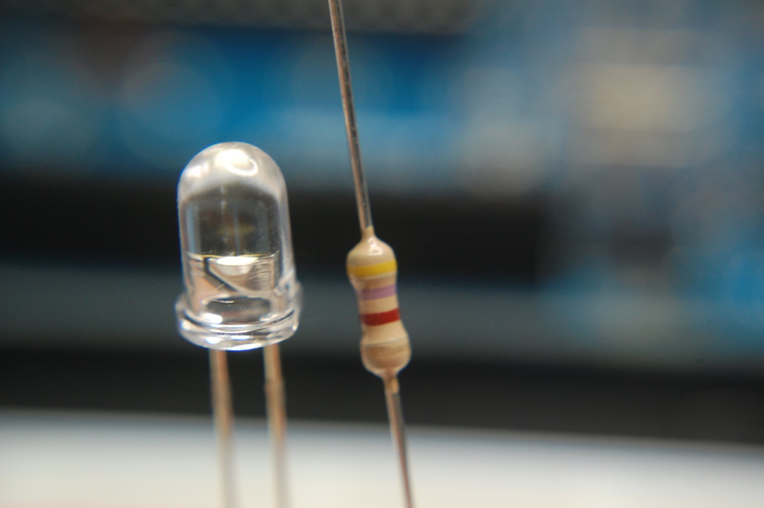
98 White LED
98 Resistor 470 ohm
Why 470?
I chose these resistors for this reason:
LED (ultrabrightness white) http://www.robot-italy.com/product_info.php?products_id=421 forward v is 3,3v and 25ma
,the clock will run to 9v and i want that the led will be drived at half current 12,5ma (no needs too much brightness), so:
(9-3,3)/0,0125= 456, correct misure is 470 ohm resistor.
Step 3: 2) the Materials -Standalone Arduino
On the web and on Instructables you will find several examples , these are the materials I used for my own PCBs, I plan to switch directly the ATMega 328 bootloader included with that my own Arduino UNO.
-2 ceramic capacitor 22pF
-quartz 16 mhz
-2 elettrolitic capacitor 100 nF
-5v regolator voltage 78L05
-1n4007 diode
-2 ceramic capacitor 22pF
-quartz 16 mhz
-2 elettrolitic capacitor 100 nF
-5v regolator voltage 78L05
-1n4007 diode
Step 4: 3) the Materials - Integrated
3- HCF4094 shift register
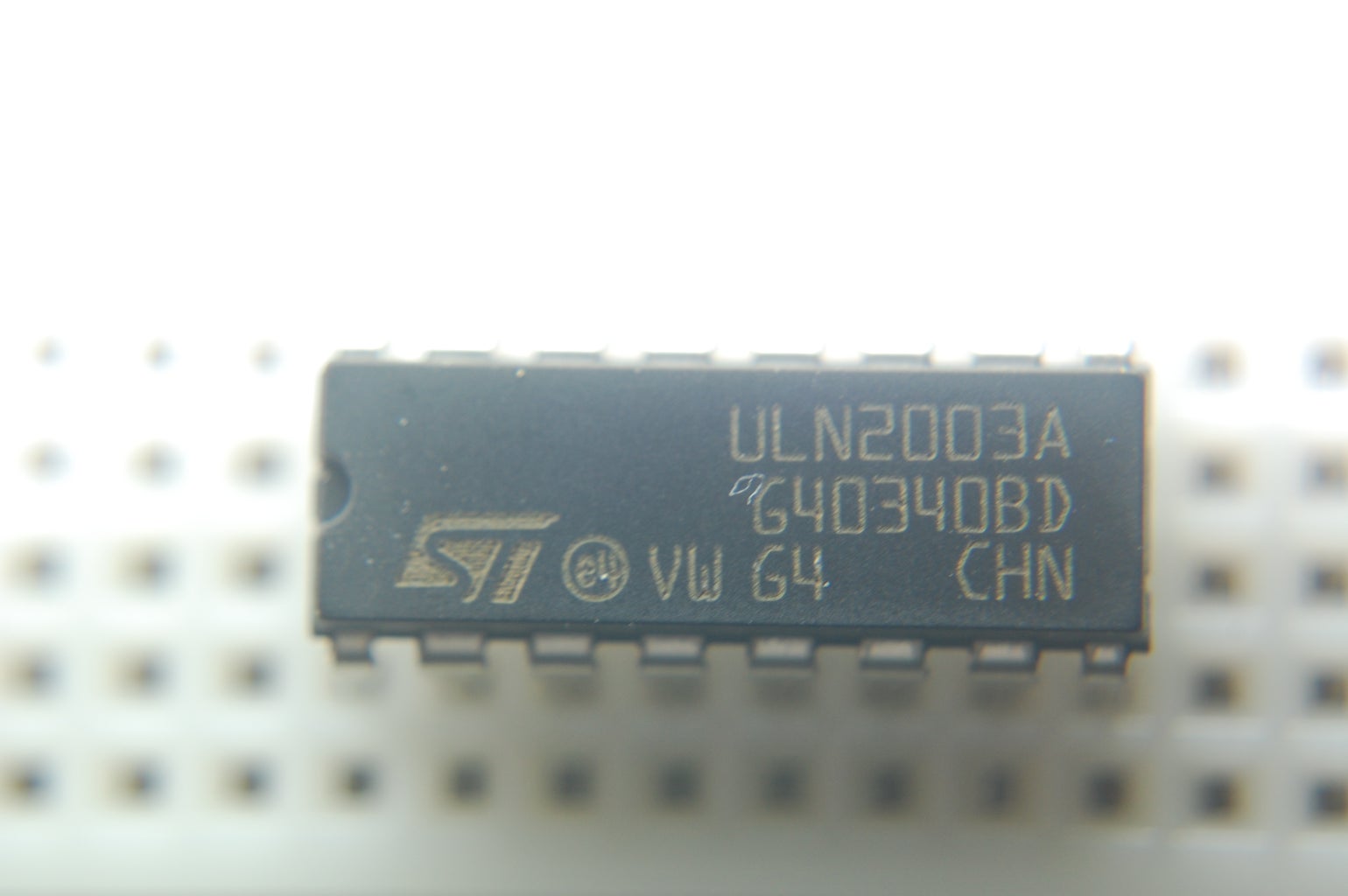
4- ULN2003A Driver
ATMega 328 with bootloader
4- ULN2003A Driver
ATMega 328 with bootloader
Step 5: 3) the Materials - Other Electronic Part
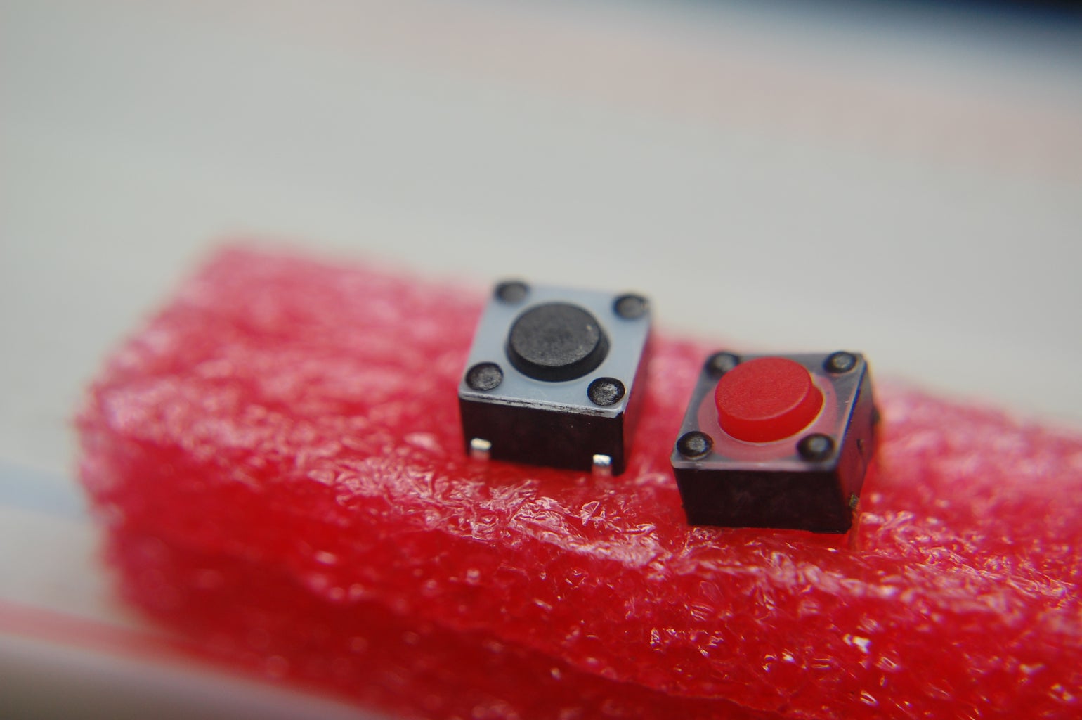
-2 micro button to set hours and minutes
-a supply voltage coaxial connector
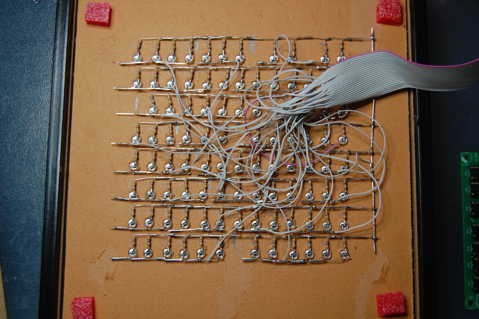
-a flat wire 26 wire with connector
-two-pole connector
-a supply voltage coaxial connector
-a flat wire 26 wire with connector
-two-pole connector
Step 6: 4) the Materials - Remainder

-IKEA Ribba frame
-carboard light, color you want to make passpartout
-cartonboard thicker to make LED holder
-carboard light, color you want to make passpartout
-cartonboard thicker to make LED holder
Step 7: LED Soldering
Bend direction, anode on top right and cathode dow left
Trip the anode and a side of resistor about 2-3 mm and sold it.
Trip the anode and a side of resistor about 2-3 mm and sold it.
Step 8: Holes Guide
Positive mask to help to do the holes in a led holder
I've used a a drill with a bit of 5mm
IKEA frame with inside lucid paper with word printed through a laser print (four lucid together are need to have a solid color black).
I've used a a drill with a bit of 5mm
IKEA frame with inside lucid paper with word printed through a laser print (four lucid together are need to have a solid color black).
Step 9: LED Holder Back
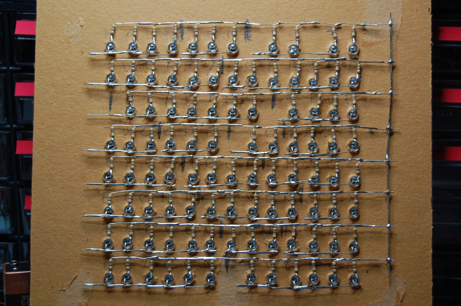
Led Holder back. Very important to bend in a short curve anode and cathode so don't risk to touch the rows together. Sold all the anodes and cathodes together but interrupt the cathodes between the words. In this mode you will have a parallel connection
after you have soldered all the end of anodes that you see on the right. In each cathode word you will sold a wire that will go to a pin to driver the word with the Arduino sketch.
after you have soldered all the end of anodes that you see on the right. In each cathode word you will sold a wire that will go to a pin to driver the word with the Arduino sketch.
Step 10: LED Holder Front
Led holder front, better black color to prevent reflection
Add some buffles to prevent the light from bleeding between words.
Add some buffles to prevent the light from bleeding between words.
Step 11: Layers
For a better spread of light and have a solid black I have four layers overlapped acetate, at the end I put a layer of gray and a white matt

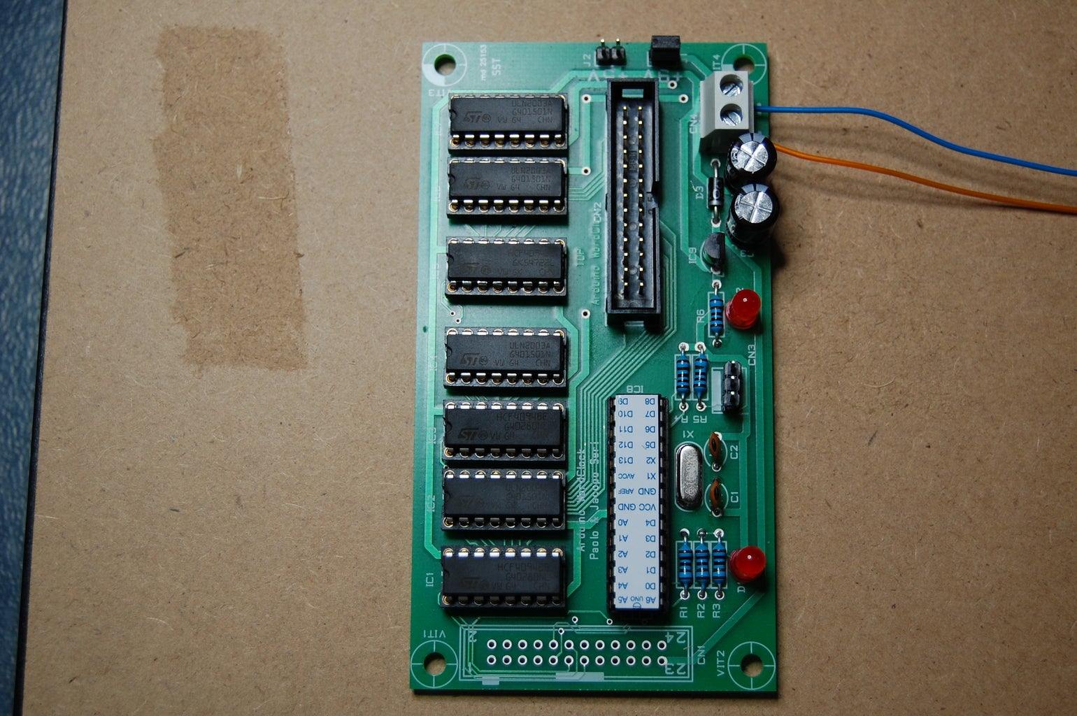
Step 12: The PCB Board

This is my personal board double layer. Has made by a professional mastering, you can easly solder all the component and have an Arduino standalone, It works 9v or 5v supply, better 9v however.
I can send gerber file for a small fee.
I can send gerber file for a small fee.
Attachments
Step 13: Supply Voltage Plug Connector
Step 14: Final Result
Step 15:
I have used the very useful and well done Doug Jackson program that reduce brightness when you want in the day time.

