Introduction: OSOYOO Arduino Robot Car
Please follow us on facebook, find our new released item and share your idea and Video on how to creatively use our products. You can get cash back or giveaway from us!
You can buy this OSOYOO robot car kit from:
OSOYOO robot car kit(OSOYOO.store)
Facebook: https://www.facebook.com/pg/OsoyooProducts
Youtube: https://www.youtube.com/playlist?list=PLvCUFipQZCUtstVBU-7gLYCLhI1fRuca3
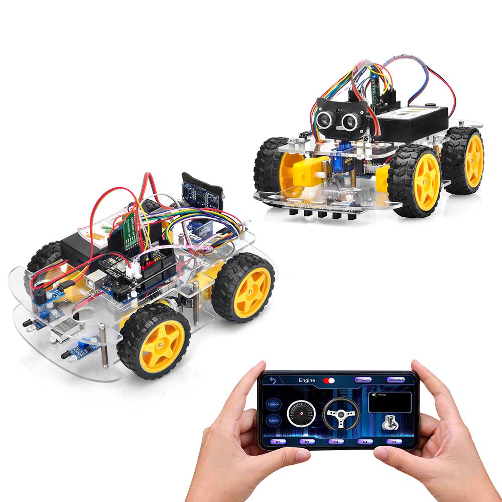
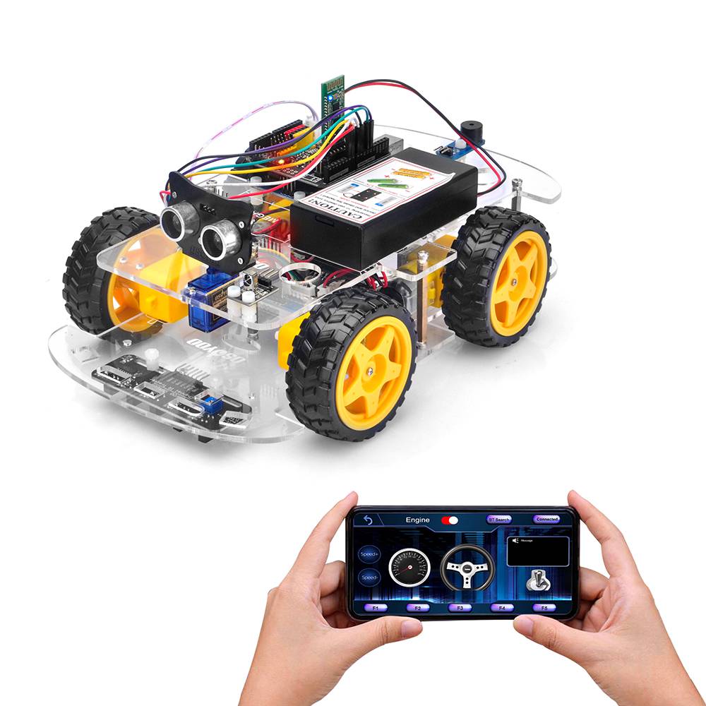
OSOYOO robotic car learning kit is designed for beginners to learn Arduino programming and get hands-on experience on robot design and assembly.
We have developed a step-by-step tutorial which evolves from a simple car without any control to a multi-function robotic car controlled by a mobile APP.
Every lesson has detailed sample code with comments, circuit graph, assembly instruction and video. Even if you have no programming experience, you can follow the step-by-step instruction and gradually become a master.
Our robotic car is 100% open source. If you are an intermediate player and have time to read our code comments, you can easily customize this robotic car to make your own project for science fair, college homework or even commercial applications.
This kit contains module parts including L298NPro motor driver module(*), Ultrasonic Sensor module, Tracking module, Infrared Remote Control, Bluetooth module and ESP8266 Wi-Fi shield, etc. With these modules, the robot car can work in multiple modes such as auto-go, infrared control, obstacle avoidance and line tracking. You can use our Android APP to change working mode through Wi-Fi or Bluetooth.
*L298NPro motor driver module is an improved L298N module which has newly designed wiring sockets and can greatly simplify the assembly procedure and wire connection stability.
Packing list:
- 1x UNO R3 board with USB cable
- 1x OSOYOO ESP8266 Uart WIFI shield
- 1x Bluetooth module
- 1x OSOYOO Model X motor drive board (an improved L298N module)
- 1x 5 channel Tracking sensor module
- 1x SG90 servo Motor
- 1x Ultrasonic Sensor module
- 1x Buzzer sensor module
- 1x IR Receiver Module
- 1x IR Transmitter Module
- 1x IR Remote controller
- 2x IR obstacle sensor
- 1x Voltage meter
- 1x Box for 18650 3.7V battery
- 1x lower chassis
- 1x upper chassis
- 4x Wheel
- 4x Gear Motor with wires
- 4x Stand holder for gear motor
- 1x Mount Holder for Ultrasonic Sensor
- 1x 20pin Jumper wires female to female
- 1x 20pin Jumper wires male to female
- 1x 6Pin Male to Female Jumper
- 1x 7Pin Female to Female Jumper
- 1x Cross Screwdriver
- 1x Screws & Nuts package for Sensor and Module Assembly
- 1 pair battery with battery charger
Step 1: Install UNO R3 Board and Motors on Chassis
1) Remove the protective film on upper and low car chassis (Each car chassis has one protective film)

2) fix 4 motors with Metal Motor Holders as follows (Please check the motor direction before installing metal motor holders)
3) Fix 4 motors on lower car chassis with screw M3*10 hex screws via hex screwdriver (screws for this step are in metal motor holder package)

4) Install OSOYOO MODEL X motor driver module to lower car chassis with 4pcs M3 plastic screws, plastic pillars and plastic nuts. (Please make sure you install the OSOYOO MODEL X motor driver module in the correct direction.)

5) Install voltage meter on low car chassis with 2pcs M3 plastic screws, plastic pillars and plastic nuts

6) Fix OSOYOO basic board on upper car chassis with 4pcs M3 plastic screws, plastic pillars and plastic nuts. (Please install board at the side with printing)

7) There are two kinds of robot car set for you to choose to buy. The one is with 2 battery box (18650 battery box and 9V battery box), and the other one is with 1 pair 18650 batteries and 1 piece battery charger for 18650. We recommend to use 18650 batteries as the power. If you want to use 9V battery as the power, please use rechargeable 9V battery. Don’t use Carbon zinc battery, as this can’t provide enough current for the robot car.
A) Fix this Battery Box on upper chassis with 4pcs M3 x 10 screws and M3 nuts.

B) Please install this Battery Box on upper chassis with 4pcs M3 x 10 screws and M3 nuts. (these are the same as screws and nuts for 18650 battery box. If you don’t get 9V battery case, please ignore this step).

7) Insert OSOYOO Uart Wi-Fi shield V1.3 onto your board

CONNECTION
1) CONNECT 4 MOTORS TO OSOYOO MODEL X MOTOR DRIVER MODULE K1 TO K4 SOCKETS AS PER FOLLOWING GRAPH:
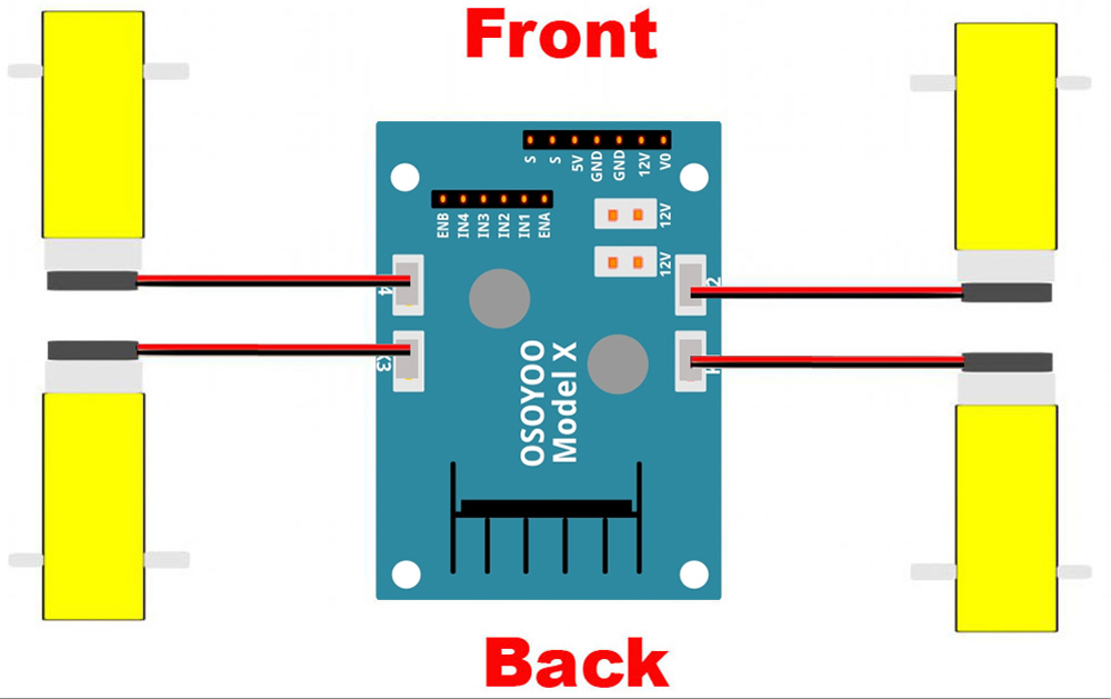
2) Connect Voltage Meter to OSOYOO MODEL X motor driver module with 3pin female to female jumper wire as below connection diagram

3) Connect OSOYOO MODEL X motor driver module 6 control pins to OSOYOO Uart Wi-Fi shield V1.3 D6, D7, D8, D9, D11, D12 with 6pin male to 6pin female jumper wire, and 12V-GND socket to VIN-GND socket with OSOYOO 2pin PnP cable 20 cm as per following graph

Caution:
When insert/remove this 6-pin plug into Model X 6-pin male socket, please hold the plastic pin-holder to do operation. Never drag the wires to pull the plug out of the socket, otherwise it will damage the wires.
4) Connect battery box (battery box for 18650 batteries or for 9V battery) to VIN-GND socket of OSOYOO Uart Wi-Fi shield V1.3 according to connection diagram


5) Connect upper chassis to lower chassis with five copper pillars and fix copper pillars with 10pcs M3*10 hex screws, then install 4 wheels onto the motors. (Please loosen the screws on the wheel if some of the wheels don’t move)


Now hardware installation is almost down. Before we install 18650 batteries into the box, we need to burn the sample code into the board First.
Software Installation:
Step 1: Install latest DE (If you have IDE version after 1.1.16, please skip this step). Download IDE from https://www.arduino.cc/en/Main/Software?setlang=en, then install the software.
Step 2: Download Lesson One sample code from https://osoyoo.com/driver/v2smartcar-lesson1.zip, unzip the download zip file smartcar-lesson1.zip, you will see a folder called v2smartcar-lesson1.
Step 3: Connect board to PC with USB cable, Open Arduino IDE → click file → click Open → choose code “v2smartcar-lesson1.ino” in smartcar-lesson1 folder, load the code into board.
Step 4: Choose corresponding board/port for your project, upload the sketch to the board.
Final Testing:
Note:
1) Recommend 18650 batteries as these batteries can make the car run smoothly.
2) The 18650 batteries we used in lessons are around 65 mm (2.56 inch) long, without an internal protection circuit.
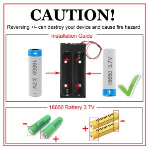
3) Check the box instruction and make sure polar direction is correct, otherwise it can destroy your device and cause fire hazard.
Please install your 18650 batteries in battery box for 18650 as per following instruction:
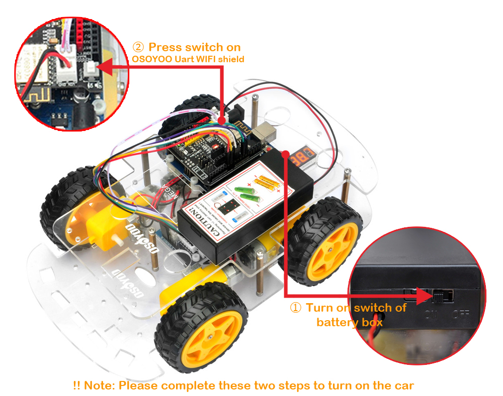
Disconnect robot car from PC, put battery into battery box. When you put the car on the ground and turn on the switch on OSOYOO Uart Wi-Fi shield V1.3 and the switch on battery box if you install battery box for 18650, the car should go forward 2 seconds, then go backward 2 seconds, then left turn for 2 seconds, then right turn for 2 seconds, then stop. (If the car does not move as per above-mentioned result, you should check your wire connection, battery voltage (must over 7.2v).)
Step 2: Control Robot Car Through Infrared Remote
Hardware Installation:
Step 1: Install the smart car basic frame work as per Step 1. If you have already completed installation in Lesson 1, just keep it as is.
Step 2: Add an IR receiver module onto the car. Install the IR receiver module with 2pcs M3 plastic screws, M3 plastic pillars and M3 plastic nuts at the front of upper chassis.

Step 3: Connect the S pin in IR receiver to D10 pin in your board, GND to GND, VCC to 5V, as the following photo (Remember : DO NOT remove any existing wires installed in Lesson 1 ) :

Software Installation:
Step 1: Install latest IDE (If you have IDE version after 1.1.16, please skip this step)
Download IDE from https://www.arduino.cc/en/Main/Software?setlang=en , then install the software.
Step 2: Install IRremote library into IDE (If you have already installed IRremote library, please skip this step)
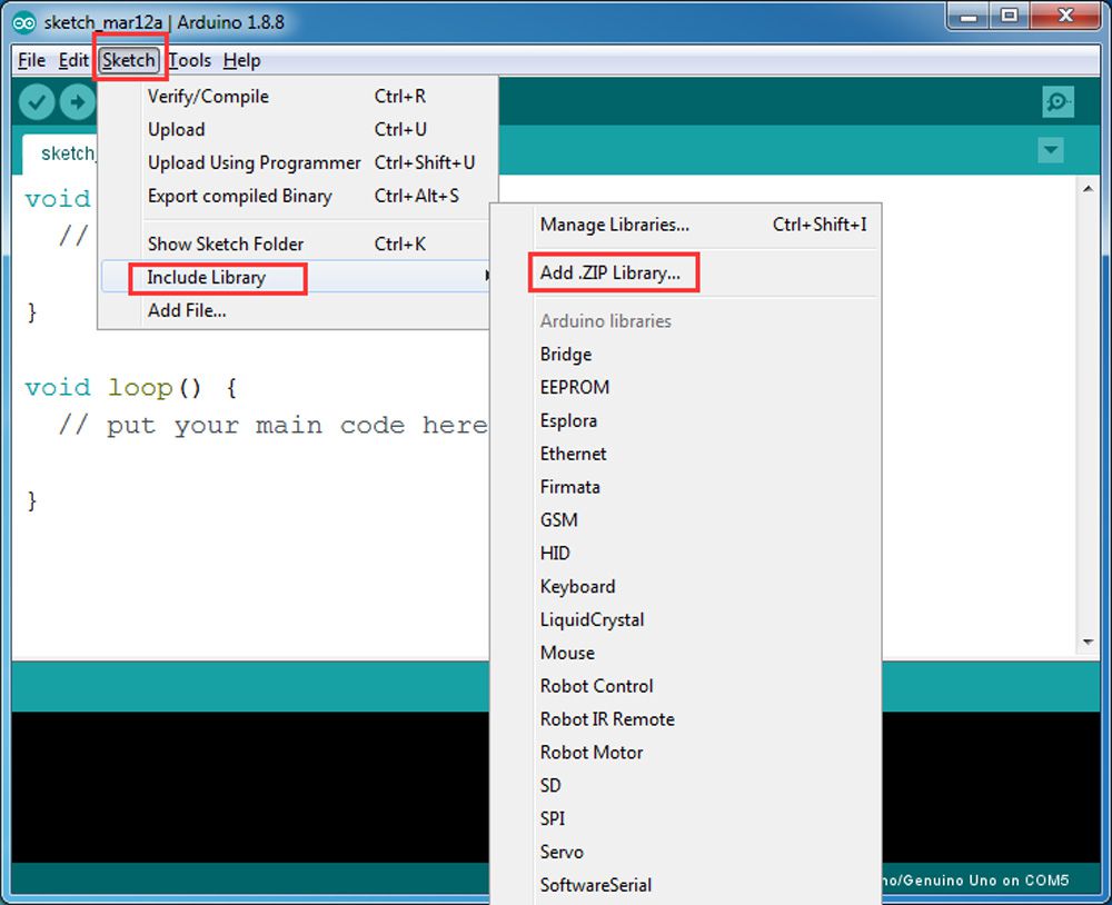
Download IRremote library from https://osoyoo.com/wp-content/uploads/samplecode/IRremote.zip, then import the library into IDE(Open IDE-> click Sketch->Include Library->Add .Zip Library)
In the pop up window, go to your downloads folder, select the IRremote.zip file you downloaded just now.

Step 3: Download Lesson 2 IRremote smart car sample code from https://osoyoo.com/driver/v2car-lesson2.zip and unzip the download zip file smartcar-lesson2.zip, you will see a folder called smartcar-lesson2.
Step 4: Connect your board to PC with USB cable, Open IDE -> click file -> click Open -> choose code “smartcar-lesson2.ino” in smartcar-lesson2 folder, load the code into your board.
Step 5: Choose corresponding board and port for your project,upload the sketch to the board.

Testing:
Press IR controller keys to control the car movements as per following instruction table:
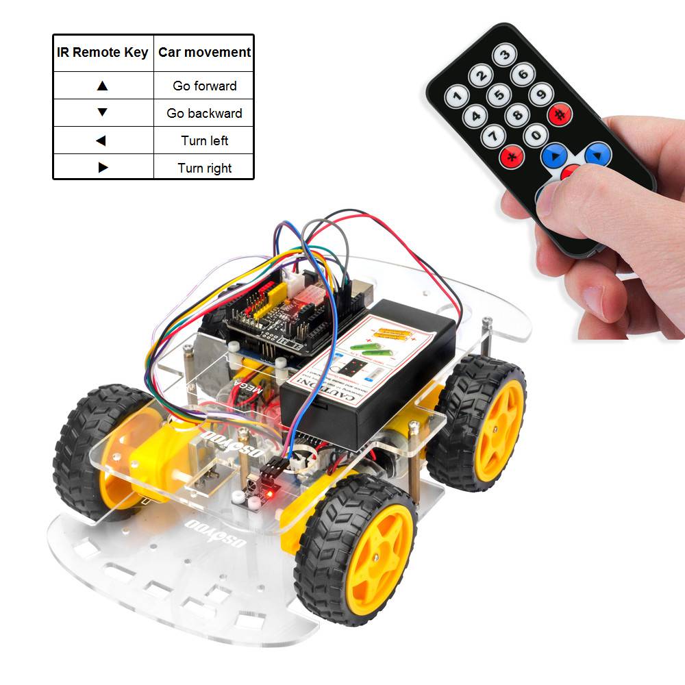
Note:
1) Please try to align the transmitter port of the IR remote control with the IR receiver head as the picture in the attachment.
2) Please press remote control gently and at regular intervals

Trouble shooting:
Some user found that this IR remote does not work. The reason might be the IR remote sends different button code which does not match our sample code. In order to solve this problem. Please take following steps:
Step A) Get the IR code of each button in your IR remote.
Copy code from following link:https://osoyoo.com/wp-content/uploads/samplecode/irdemo.ino
upload above sketch into your board and open the serial monitor in your upper-right corner.

press the ◄ ► ▲ ▼ “OK” button in your remote, you will see their IR code as following picture:
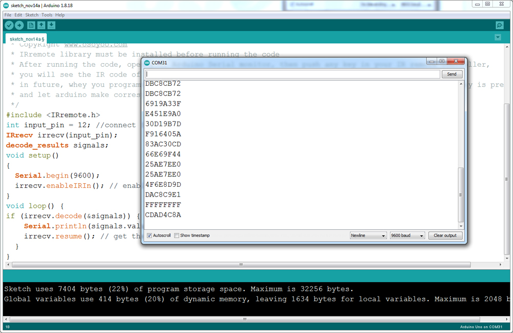
Write down the IR code of your control buttons ◄ ► ▲ ▼ “OK” button,
STEP B)replace the IR code in lesson 2 sketch file:
Open your Lesson 2 code again, then you will see following lines define the IR CODE of each button:
#define IR_ADVANCE 0x00FF18E7 //code from IR controller “▲” button
#define IR_BACK 0x00FF4AB5 //code from IR controller “▼” button
#define IR_RIGHT 0x00FF5AA5 //code from IR controller “►” button
#define IR_LEFT 0x00FF10EF //code from IR controller “◄” button
#define IR_STOP 0x00FF38C7 //code from IR controller “OK” button
#define IR_turnsmallleft 0x00FFB04F //code from IR controller “#” button
Please change the value of each button in above lines to match the code from Step A). If you don’t know how to change, just Send Email to us and give us the code of each button from Step A), I can help you to change the code and email new sketch file to you.
Above method can also allow you to use other IR sending device (i.e TV remote, DVD remote, air conditioner remote etc) to control the car. Just use Step A) to get the key code of your remote and change the sketch file in Step B), it will work.
Note:
1) Please try to align the transmitter port of the IR remote control with the IR receiver head as the picture in the attachment.
2) Please press remote control gently and at regular intervals
 .
.
Step 3: Object Follow Robot Car
Install devices
Step 1: Install the smart car basic frame work as per Step 1. If you have already completed installation in Lesson 1 , just keep it as is.
Step 2: Remove the screws on copper pillars and add 2pcs IR distance sensor onto the car. Install the IR distance sensors with 2pcs M3 plastic screws, M3 plastic pillars and M3 plastic nuts at the back of low car chassis.

Step 3: Connect 2pcs IR distance sensors modules as below connection diagram (Remember : DO NOT remove any existing wires installed in Lesson 1 ) :

Step 4: Fix the screws on copper pillars to connect upper chassis to lower chassis.

SOFTWARE INSTALLATION:
Step 1: Install latest IDE (If you have IDE version after 1.1.16, please skip this step)Download IDe from https://www.arduino.cc/en/Main/Software?setlang=en , then install the software.
Step 2: Download Lesson 3 sample code from https://osoyoo.com/driver/v2smartcar-lesson3.zip , unzip the download zip file v2smartcar-lesson3.zip, you will see a folder called v2smartcar-lesson3 .
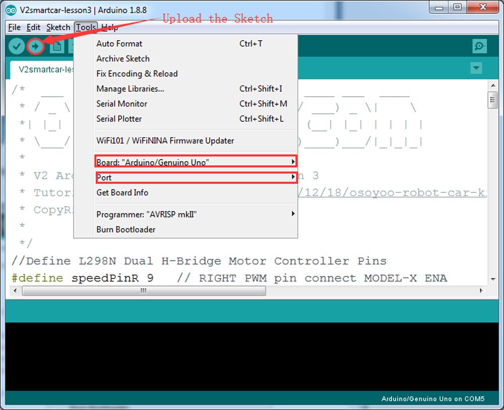
Step 3: Connect OSOYOO basic board to PC with USB cable, Open Arduino IDE -> click file -> click Open -> choose code “v2smartcar-lesson3.ino” in v2smartcar-lesson3 folder, load the code into your board.

Step 4: Choose corresponding board/port for your project,upload the sketch to the board.
Step 5: Turn on the car, put object about 10cm ahead of each IR distance sensors and adjust potentiometer on IR distance sensors to detect object or your hand.
Note: When these module detect objects, the power indicator and signal indictor are on. when you move object over detection distance, the power indicator is on. If the signal indictor is always on even though the object is over detection distance, you also need to adjust the potentiometer

FINAL TESTING :
Turn on the car, move the object or your hand ahead of the car, and then the car will move accordingly: looks like you pull it. It goes forward when both IR Obstacle Avoidance modules detect object or your hand; it turns right when the right IR Obstacle Avoidance modules detect object; it turns left when the left IR distance sensors detect object.
When the object or your hand is over 10 cm ahead, it will stop.
Note:
1) As IR distance sensors modules are installed at the back of the car, all movement directions are contrary to other courses.
2) The car can only move forward, turn right and turn left, but cannot move backward.

Step 4: Tracking Line Robot Car
Hardware Installation:
Step 1: Motor driver(Model-X)pin installation.
Start the installation from previous status of Step 1. If you have installed Step2 or Step3, you must remove the wires which you connected in step2 and step3.
Step 2: Install tracking sensor modules under lower car chassis with 2pcs M3 plastic screws, M3 plastic pillars and M3 plastic nuts.

Step 3: Connect GND-VCC pin of tracking sensor module to GND-5V of OSOYOO Uart Wi-Fi shield V1.3; connect IR1, IR2, IR3, IR4, IR5 pins to A0, A1, A2, A3, A4 with 7pin 25 cm female to female cable as the following photo shows (Remember : DO NOT remove any existing wires installed in Lesson 1 ):

Software Installation:
Step 1: Install latest IDE (If you have IDE version after 1.1.16, please skip this step). Download IDE from https://www.arduino.cc/en/Main/Software?setlang=en, then install the software.
Step 2: Download Lesson 4 tracking smart car sample code from v2smartcar-lesson4, unzip the download zip file smartcar-lesson4.zip, you will see a folder called smartcar-lesson4B.
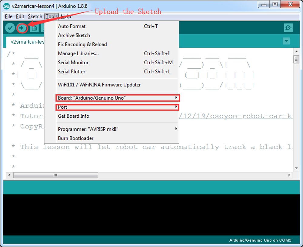
Step 3: Connect OSOYOO basic board to PC with USB cable, Open IDE -> click file -> click Open -> choose code “smartcar-lesson4.ino” in smartcar-lesson4 folder, load the code into your board.

Step 4: Choose corresponding board/port for your project, upload the sketch to the board.
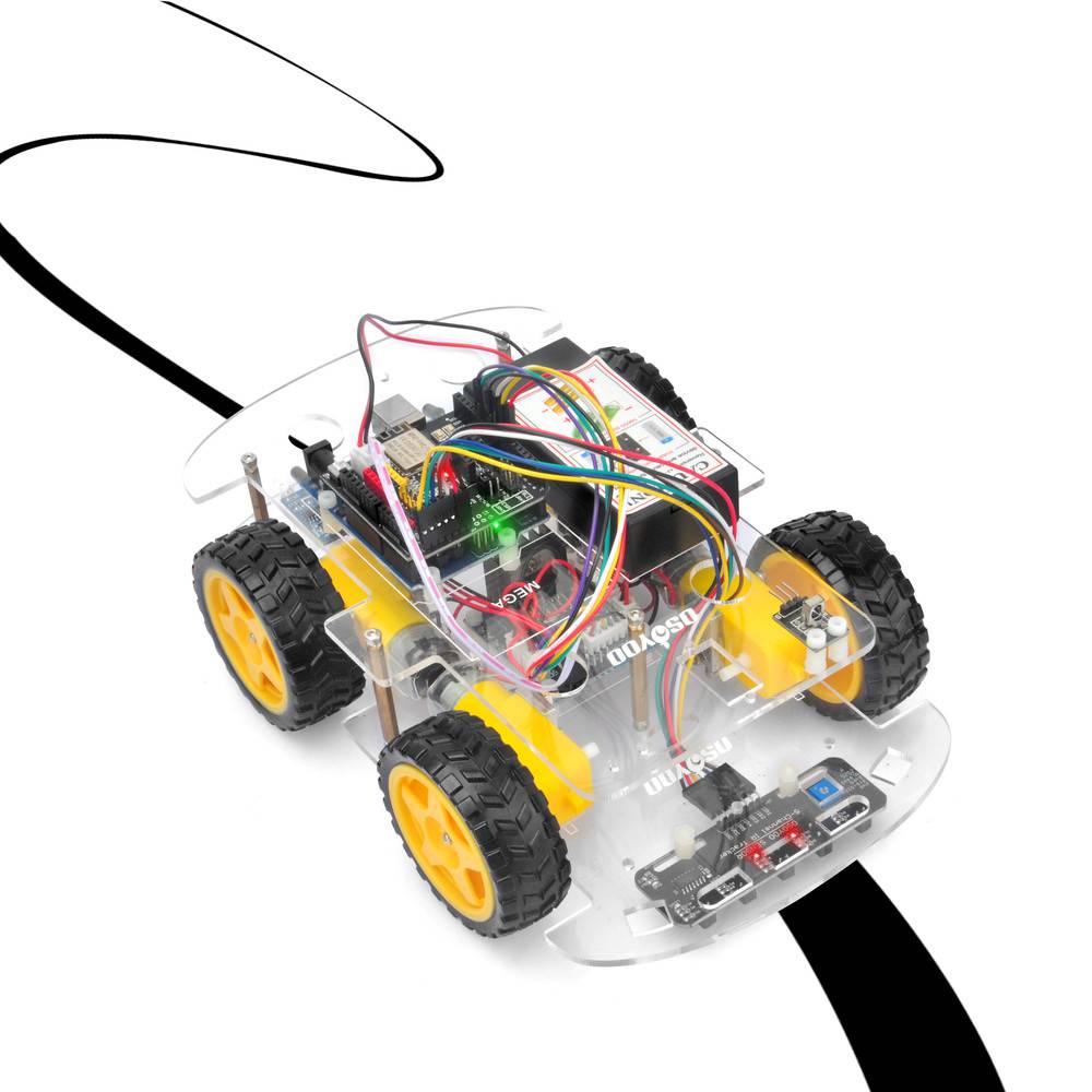
Step 5: Adjust the sensitivity of tracking sensor modules. Turn on and hold the car and adjust the potentiometer on the tracking sensor with Philips screwdriver until you get the best sensitivity status: the signal indicates LED light will turn on when the sensor is above black track, and the signal LED will turn off when the sensor is above white ground

Testing:
Prepare a black track (the width of the black track is more than 20 mm and less than 30 mm) in white ground. Please note, the bend angle of track can’t be larger than 90 degree. If the angle is too large, the car will move out of the track.
Turn on the car and put the middle of the tracking sensor module facing over the black track, and then the car will move along the black track.
Step 5: Obstacle Avoidance Robot Car
Hardware Installation
Step 1: Install the smart car basic frame work as per Step 1. If you have already completed installation in step1 , Everything keep it as is except move ENA from D9 to D3(we need D9 for Servo control). If you have installed step2 or 3, you can remove the wires. If you have installed step 4, you can keep it.
Step 2: Install servo motor at the front of upper car chassis with 2pcs M2.2*8 Self Tapping Screws

Step 3: Install Ultrasonic Module to mount holder with 4pcs M1.5*8 screw and M1.5 nuts
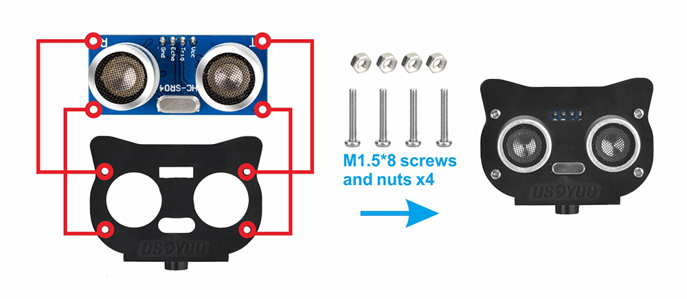
Step 4: Install mount holder for Ultrasonic Module on servo motor with M2*4 Self Tapping screw

Step 5: Install Buzzer module at the back of upper chassis with 1pc M3 plastic screw, M3 plastic pillar and M3 plastic nut

Step 6: Connect SG90 servo motor, OSOYOO MODEL X motor driver module and OSOYOO Uart WiFi shield V1.3 as following grape:

Step 7: Connect ultrasonic module, Buzzer module with OSOYOO Uart WiFi shield V1.3 as below connection diagram

Step 8: Fix the screws on copper pillars to connect upper chassis to lower chassis if you remove these.

Software Installation:
Step 1: Install latest Arduino IDE (If you have Arduino IDE version after 1.1.16, please skip this step). Download Arduino IDE from https://www.arduino.cc/en/Main/Software?setlang=en, then install the software.
Step 2:Download sample code from https://osoyoo.com/driver/v2smartcar-lesson5.zip, unzip the download zip file smartcar-lesson5.zip, you will see a folder called v2smartcar-lesson5.
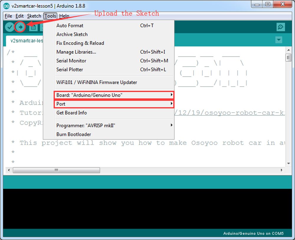
Step 3: Connect Arduino UNO to PC with USB cable, Open Arduino IDE -> click file -> click Open -> choose code “v2smartcar-lesson5.ino” in smartcar-lesson5 folder, load the code into Arduino. (Notice: Please turn off battery power when your Robot is connected to Personal Computer or Laptop via USB cable)
Step 4: Choose corresponding board/port for your project, upload the sketch to the board.
Step 5:Ultrasonic sensor servo initial direction alignment
After turning on the battery, you will hear a long beep sound, then the servo will make some movement and finally stops at a direction for 5 seconds.
During this first 5 seconds, you must make sure the Ultrasonic sensor(two eyes) is facing straight forward.
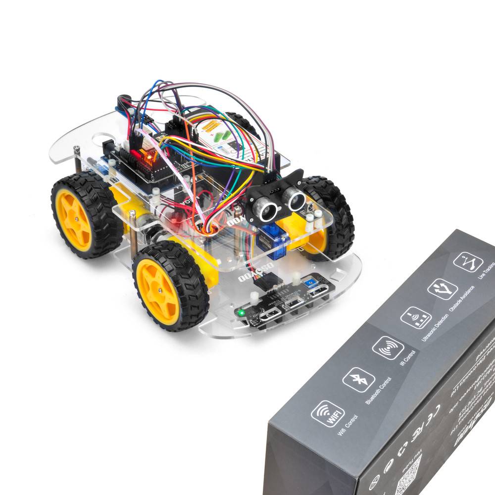
If it is not straight forward, you should turn off battery immediately and remove the sensor from servo, reinstall it and make it facing straight forward direction as following picture. Otherwise, the obstacle avoidance program will not work properly.
After adjusting sensor direction, turn on battery again. After hearing the long beep, the sensor should face front, same as the following picture. If its direction is not straight forward, turn off battery and do direction alignment again.

Final Testing :
After turning on the battery switch on the battery box, if the ultrasonic module turn to front view position, that means you don't need to adjust sensor position anymore. Just wait 5 seconds. If no obstacle is detected, the car will go forward. If any obstacles are detected, the car will stop, the ultrasonic module will turn from right to left to detect surrounding obstacle. The robot car will decide to make left turn, right turn or backward according to obstacle sensor data and our obstacle avoidance algorithm.
Sometimes your car might have collision and make your Ultrasonic sensor position change, you must remember to do sensor direction alignment again as per link Ultrasonic sensor servo initial direction alignment
Trouble Shooting
Is there an easy way to align my Ultrasonic sensor to make it facing front?
Step 1) Download https://osoyoo.com/driver/arduino_servo_car/servo.zip
Step 2) Unzip above file and run the servo.ino file in your car.
Your servo will move from left to right and finally stop to centre position. If your ultrasonic sensor is not facing to front direction. Please release your ultrasonic sensor from the servo head, re-position its direction to front, then fasten the sensor screw to fix its direction. See video from 7:4 to 8:10
Step 3) After you have changed the sensor direction, please run v2smartcar-lesson5.ino sketch again. Your car will begin to do obstacle avoidance driving.
Step 6: Use WIFI to Control an IoT Robot Car
Hardware Installation :
Step 1: Install the smart car basic frame work as per Step5, If you don’t install tracking sensor module, please complete installation in Step4.
Step 2: Connect E_TX (Esp8266 TX) pin to D4(soft serial RX for UNO) and E_RX(ESP8266_RX) pin to D5(software serial TX for UNO) as per following picture
(Note: Our OSOYOO Uart WiFi shield V1.3 are connected BLE URAT TX/RX ports to D4,D5 with jumper caps by default. If you find the BLE URAT TX/RX ports are connected, you need to remove these jumper caps and change to connect ESP URAT E-TX to D4 and E-RX to D5)

Step 3: Connect SG90 servo motor, OSOYOO MODEL X motor driver module and OSOYOO Uart WiFi shield V1.3 as following graph (If you complete wires in lesson 5, please skip this step):

Step 4: Connect ultrasonic module, buzzer module with OSOYOO Uart WiFi shield V1.3 as below connection diagram (If you complete wires in lesson 5, please skip this step)

Step 5: Connect tracking sensor module with OSOYOO Uart WiFi shield V1.3 as below connection diagram (If you complete wires in lesson 4, please skip this step)

Note
1)Please remember to adjust the sensitivity of tracking sensor modules as per link lesson 4
2)Please remember to do Ultrasonic sensor direction alignment as per link lesson 5
Software Installation:
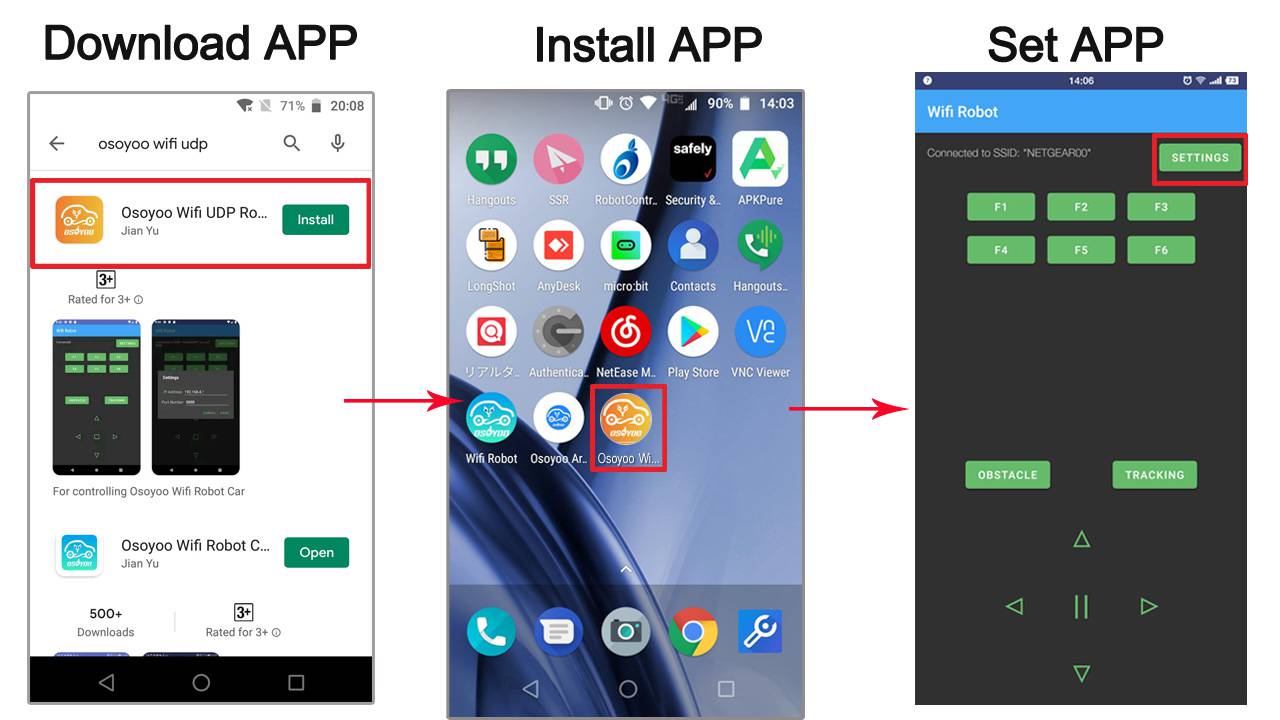
Step 1) Download OSOYOO WIFI UDP Robot Car control APP
In Google Play or Apple Store, please search key words “OSOYOO WIFI UDP Robot Car”, you will find an orange icon APP as following:
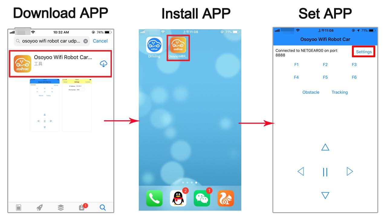
Step 2) Please download the library zip file from WiFiEsp-master .Open IDE ->click Sketch ->Include Library ->Add .ZIP library , then load above zip file into sketch.
Step 3) Sketch code Installation:
Osoyoo V2 Robot Car can work in two WIFI modes: STA mode and AP mode. The sketches for these two modes are different. Let’s explain these two modes one by one
A)STA mode
In STA mode, V2.1 Robot Car will be a client device of your LAN router. You need save the SSID name and password of your LAN router in sketch.
Once the sketch is running, your router DHCP service will assign an IP address to your robot car and your APP will use this IP address to access your car.
1) Please download STA mode sketch code from v2smartcar-lesson6A . Unzip the file, you will see a folder “v2smartcar-lesson6A”. Open IDE -> click file -> click Open -> choose code “v2smartcar-lesson6A.ino” in v2smartcar-lesson6A folder, load the code into your board
2) You need change the code Line 96 and Line 98 :
char ssid[] = “YOUR_ROUTER_SSID”; // replace this with your router wifi SSID
char pass[] = “YOUR_ROUTER_WIFI_PASSWORD”; // replace with your wifi password
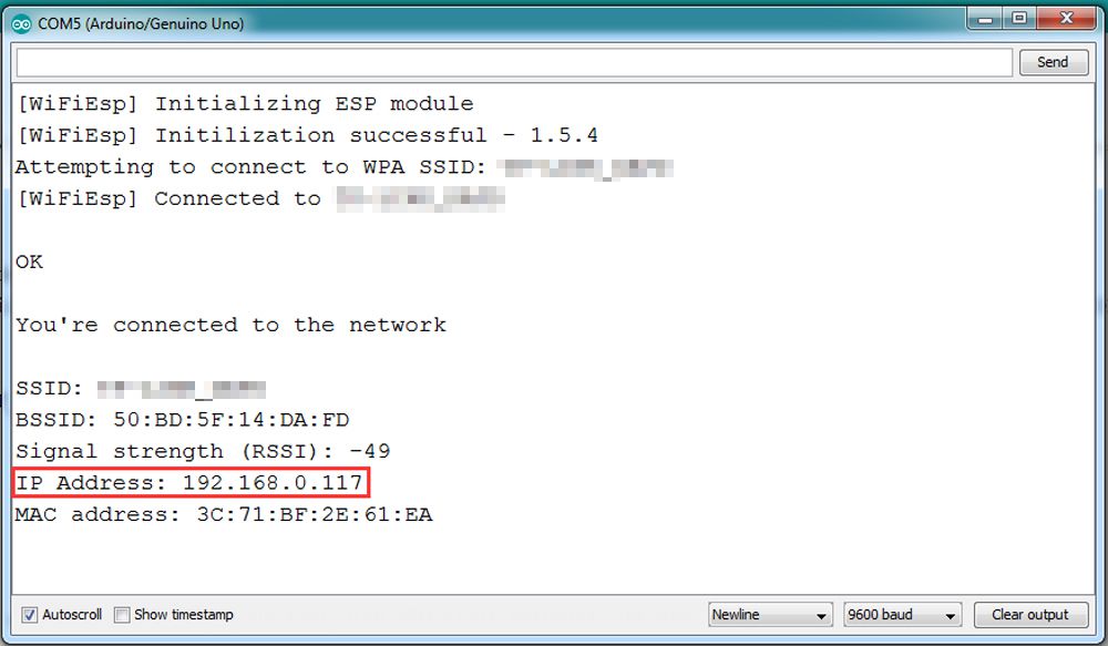
3) Upload the sketch to your board. Finally, click the Serial monitor window in upper right corner of IDE, you will see following result:
4) In this mode, your will see an IP address which is our LAN IP address assigned by my router. Please write down this IP address and click Setting to set up robot IP address and set this IP address to your APP Setting section and Port to 8888 in settings.
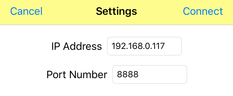
Now your Robot car is connected to your LAN, you can use Mobile phone under same LAN to control the robot car. If your APP is in WAN, you need to go to your Router Control Panel, forward Port 80 to Robot car LAN IP address, then you can use Router IP to control the car. This feature makes our robot car A REAL INTERNET OF THING device
B)AP mode
Sometimes we do not have a LAN or WIFI Router. In order to control the car, we need to use AP mode.
When working in AP mode, our robot car itself will become a WIFI Hot Spot. Our cell phone can connect to Robot Car as its wifi client. The IP address of Robot is fixed as 192.168.4.1 and It is not connected to WAN.
1) Please download sketch from following link: v2smartcar-lesson6B. Unzip the file, you will see a folder “v2smartcar-lesson6B”. Open IDE -> click file -> click Open -> choose code “v2smartcar-lesson6B.ino” in v2smartcar-lesson6B folder, load the code into your board
2) Open Serial monitor, and you will see a similar result as STA mode. A new WIFI SSID “osoyoo_robot” with IP address 192.168.4.1 will show up in the window. This means your Robot car has a WIFI Hot Spot name “osoyoo_robot” , its IP address is 192.168.4.1
3) Connect your cell phone to “osoyoo_robot” wifi hot_spot, and set IP address as “192.168.4.1” and port to 8888 to your APP Setting section
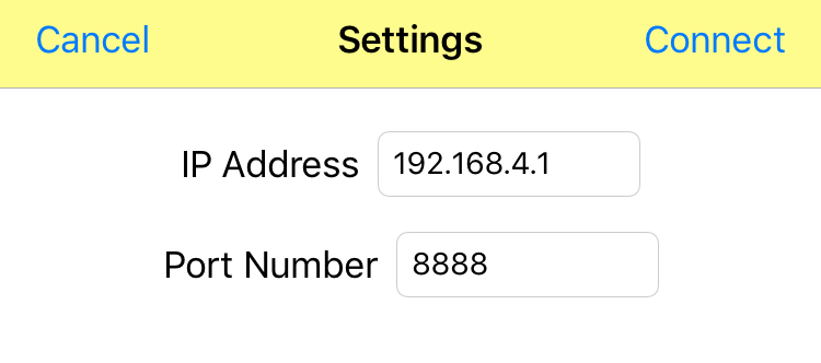
Now your Robot car become a WIFI Hot Spot, you can use Mobile phone control the robot car.
FINAL TESTING:
Trun on the car. Now click Setting to set up robot IP address.
A) In STA mode, you need connect cell phone to the same LAN ssid of your robot car and set IP address same as the Robot IP showed in Serial Monitor.
B) In AP mode , you need contact your cell phone to “osoyoo_robot” wifi hot_spot and set IP address as 192.168.4.1
you can click the ◄ ► ▲ ▼ direction keys to make the car move. Use || pause key to stop the car movement.
If you click Obstacle key, the car will do obstacle avoidance auto driving similar to Lesson 5
If you click Tracking key, the car will do link tracking auto driving similar to lesson 4
Note: F1~F6 are further development functions in the future.
FAQ about the WIFI UDP APP and sketch Code:
Q1)How to tune the robot car speed?
A: If you want change the speed performance of the robot car, please following parameters in line 11 to 13:
#define SPEED 85
#define TURN_SPEED 90
#define SHIFT_SPEED 130
SPEED value determines forward moving speed
TURN_SPEED value determines turning speed
SHIFT_SPEED value determines parallel shifting speed
Q 2)What happened when you press buttons in OSOYOO WiFi UDP Robot Car APP ?
A: When you press a button of the APP, APP will send a single-letter message through UDP protocol to target device (in this example, our WIFI Shield)
ButtonUDP messageF1FF2GF3HF4IF5JF6K▲A▼B►R◄LsquareEobstacleOtrackingT
Q3)How does the board handle the UDP command?
Following switch(c) statements in v2smartcar-lesson6 sketch file are handling the UDP command
            switch (c)    //serial control instructions
            {

               case 'A':Drive_Status=MANUAL_DRIVE; Drive_Num=GO_ADVANCE;  WorkMode="GO_ADVANCE";break;
               case 'L':Drive_Status=MANUAL_DRIVE; Drive_Num=GO_LEFT; WorkMode="GO_LEFT";break;
               case 'R':Drive_Status=MANUAL_DRIVE; Drive_Num=GO_RIGHT;WorkMode="GO_RIGHT";break;
               case 'B':Drive_Status=MANUAL_DRIVE; Drive_Num=GO_BACK;WorkMode="GO_BACK";break;
               case 'E':Drive_Status=MANUAL_DRIVE; Drive_Num=STOP_STOP;WorkMode="STOP_STOP";break;
               case 'O':Drive_Status=AUTO_DRIVE_UO;Serial.println("go OBSTACLE");WorkMode="OBSTACLE";break;
               case 'T':Drive_Status=AUTO_DRIVE_LF;WorkMode="line follow";break;
               case 'G':track_speed=track_speed+10;
                        if(track_speed>200) track_speed=200
                         ;break;
               case 'J':track_speed=track_speed-10;
                        if(track_speed<80) track_speed=80
                         ;break;
               default:break;
              } //END OF ACTION SWITCH
In above code, c in switch() brackets is the UDP data sent from cell phone APP. Once APP ▲ key is pressed, then case ‘A’ … line will handle the command and make car move ahead.
Step 7: Imitation Driving With Bluetooth APP
Hardware Installation
Step 1: Install the smart car basic frame work as per Step 1. If you have already completed installation in step 1, please remove all wires on Osoyoo WIFI expansion module
Step 2: Connect Bluetooth TX/RX ports to D4,D5 with jumper caps
Note: Our OSOYOO Uart WiFi shield V1.3 are connected BLE URAT TX/RX ports to D4,D5 with jumper caps by default. If you find the Bluetooth TX/RX ports is not connected to D4,D5, you need use a jumper cap or jumper wire to connect B-TX to D4 and B-RX to D5

Step 4: Insert Bluetooth Module into OSOYOO Uart WiFi shield V1.3 Bluetooth slot as following graph:

Step 5: Connect OSOYOO MODEL X motor driver module and OSOYOO Uart WiFi shield V1.3 as following graph:
Remember following tips restore your motor control system to lesson 1:
- If your last project is lesson 1,2,3,4, your motor control system is same as Lesson 1, no need do anything.
- If your last project is lesson 5,6, you need change ENA wire from D3 to D9, keep wiring in D6,D7,D8,D11,D12 at same position and remove all other wires in OSOYOO Uart WiFi shield V1.3.
I suggest you run the sketch code in Lesson 1 and make sure motor connection is correct. This is very important for next steps.

Software Installation;
Step 1: Install APP into your mobile phone:
1) Install APP on Android device as following
In Google Play store search APP name “OSOYOO imitation driving”, download the APP as following and install it in your smart phone
If you can not use Google Play to find the APP, please Download the APP from following link :https://osoyoo.com/driver/v1car.apk.
2) Install APP on Apple IOS device as following
In Apple APP store search APP name “OSOYOO imitation driving”, download the APP as following and install it in your smart phone
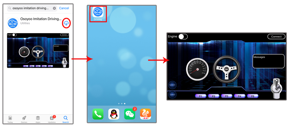
Step 2: Download and install sketch code from v2smartcar-lesson7. Unzip this file, and you will see a folder called v2smartcar-lesson7. Open IDE -> click file -> click Open -> choose code “v2smartcar-lesson7.ino” in v2smartcar-lesson7 folder, load the code into your board
 EXPLANATION OF APP UI
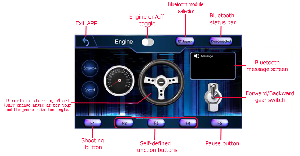
- Connect HC-02 bluetooth in Android phone. There is a BT Search button in Android APP: When click this button, you will see a Bluetooth device list which has been paired with your APP. Select HC-02 device to connect the car. Once HC-02 is connected, Bluetooth Status will change from Disconnected to Connected. You can only control your car when Bluetooth is connected.
- Connect HC-02 bluetooth in iPhone/iPad , simply click Connect button, a HC-02 device will show up in a pop-up list. Click that HC-02 device will connect Bluetooth module to your iPhone. Then the Connect button will change name to Disconnect.
- Engine toggle : When Engine toggle is set to OFF(white), car will stop and all buttons in the APP will be disabled. When Engine toggle is set to ON(red), car will start to move. All other movement control buttons will active.
- Forward/Backward gear switch: This gear switch can control the car is moving ahead or reverse like real car gear.
- F1,F2,F3,F4,F5 customized button. In this lesson, we only use F5 which pause the the car movement. The difference between F5 and Engine OFF button is that Engine OFF button when touched, all other buttons will be disabled. You should toggle Engine button again to enable other button. On the other hand, when F5 is clicked, the car will stop but all other buttons is still active. Even you do not touch any button just change your cell phone angle position(like you move the steering wheel), the car will move again.
- Direction Steering Wheel : When you rotate your mobile phone angle, the steering wheel will change angle as per your mobile phone rotation angle. This will make your car change direction. For example, when steering wheel make clockwise rotation, car will move to left. Remember, the steering and Forward/Backward gear should work together same as you are driving a real car. For example, when you want back your car to a right side packing lot, you need set Gear to R position and rotate your steer to count-clockwise direction.
- Speed+: Make the robot car speed up
- Speed-: Make the robot car slow down
Connect APP to HC-02 Bluetooth Module
- Connect with Android device:
- If you use Android device and have not paired Bluetooth module with your cell phone, please pair the bluetooth module first before open the APP. In your cell phone Setting->Bluetooth ,find a Bluetooth device called HC02, pair it with password 1234.After bluetooth HC02 device is paired, open the APP. Click BT Search Button to connect APP to HC02 device.
- Connect with iOS device:
- If you use iOS device, simply open the APP, click Connect button, you will see a Bluetooth list, select the HC02 device .
Drive your Robot Car
Now you have installed your hardware and software for this lesson, let’s drive our car!
Step 1)Put your robot car onto the ground and turn on the switch.
Step 2)Go to your mobile phone ->Setting ->Bluetooth setting and search a Bluetooth device called HC-02, pair it with code 1234
Step 3)Open OSOYOO imitation driving Robot APP, Click BT Search button and find the bluetooth you have paired
Step 4)Turn on Engine toggle, click Speed+ to make the robot speed up as the robot car is very slow at first. When you rotate your mobile phone angle, your car will change direction.
Enjoy your driving!

Step 8: Fighting Game
Hardware Installation
Step 1:This project needs at least two Osoyoo Robots. In each robot, step 7 hardware installation must have been completed.
Step 2: Install IR receiver (step 2) and buzzer module (Step 5) and add IR transmitter with 2pcs M3 plastic screws, pillars and nuts as following:

Step 3: Connect IR receiver, IR transmitter and buzzer module with OSOYOO Uart WiFi shield V1.3 as following graph

Software Installation:
Step 1: Download and install sketch code from v2smartcar-lesson8. Unzip this file, and you will see folders called v2smartcar-lesson8A and v2smartcar-lesson8B
Step 2: Upload code “v2smartcar-lesson8A.ino” in v2smartcar-lesson8A folder for Team A robots and Upload code “v2smartcar-lesson8B.ino” in v2smartcar-lesson8B folder for Team B robots
Step 3: If you have installed the APP in Lesson 7, please skip this step. Otherwise, go to Google Play and search the APP name “Osoyoo imitation driving”, and install the APP to your mobile phone.
Step 4: After install the APP, pair the HC-02 bluetooth module to your mobile phone, then open Osoyoo Imitation driving APP. You will find a BTSearch list, click HC-02 device to connect the bluetooth device on your car.
Play the Fighting Game:
In your APP, click Engine Toggle icon, your robot car will start moving. Use your steering wheel, gear to change your car direction. When you find your enemy, click “F1” to trigger bullet against bullet. If your bullet hits an enemy car, the enemy car will freeze, buzzer and dead. If you are hit by an enemy’s bullet, your car will freeze and your APP will show “dead”.
