Introduction: Obstacle Avoiding and Manual Controllable Robot Using Android Phone


Hi everyone :)
in this instructable im going to show you a simple way to make your own obstacle avoiding robot using ARDUINO and ANDROID phone to control it so follow the steps below one by one and i hope its gonna be helpful
Step 1: Some Advices Before We Go Forward

- * This project is based on Arduino so i highly recomend if you are new to arduino go check this awesome Arduino class its very helpful LINK https://www.instructables.com/class/Arduino-Class/
* i highly recommend to enroll to this awesome robots class https://www.instructables.com/class/Robots-Class/
Step 2: Parts You Need to Make This Robot

* Robot Chassis LINK https://goo.gl/3iW1CJ
* Arduino(i`m using uno) LINK https://goo.gl/2HhrW1
* L298N motor driver LINK https://goo.gl/yTgruL
* HC-SR04 ultrasonic sensor LINK https://goo.gl/uDsKTD
* HC-06 bluetooth module LINK https://goo.gl/UNVN2r
* Mini Breadboard LINK https://goo.gl/XM9cSu
* Jumper cables (male to male & female to male ) LINK https://goo.gl/wk57B5
Step 3: Some Information About the Parts We Are Using

* Arduino Uno is a microcontroller board based on the ATmega328P It has 14 digital input/output pins (of which 6 can be used as PWM outputs), 6 analog inputs as i recommend using the UNO as a beginner because its easy to use.
* HC-06 its a low cost Bluetooth module and it work perfect with the Arduino and it can work as a slave or master
* HC-sr04 its a ultrasonic sensor and can measure the distance from 2cm up to 4m and its very useful sensor
*L298N motor driver this is a great instructable for the L298N make sure to check it out https://www.instructables.com/id/Arduino-Modules-L...
Step 4: HC Sr04 Ultrasonic Connection


* connect the sensor VCC pin to pin 5V in the arduino
* connect the sensor GND pin to pin GND in the arduino
* connect the sensor TRIG pin to pin number 11 in the arduino
*connect the sensor ECHO pin to pin number 12 in the arduino
Step 5: Bluetooth Connections


* connect the module`s VCC pin to 5V pin in the arduino
* connect the module`s GND pin to GND pin in the arduino
* connect the module`s TX pin to the RX pin in the arduino which is the pin number 0
* connect the module`s RX pin to the TX pin in the arduino which is the pin number 1
Step 6: L298N Connection


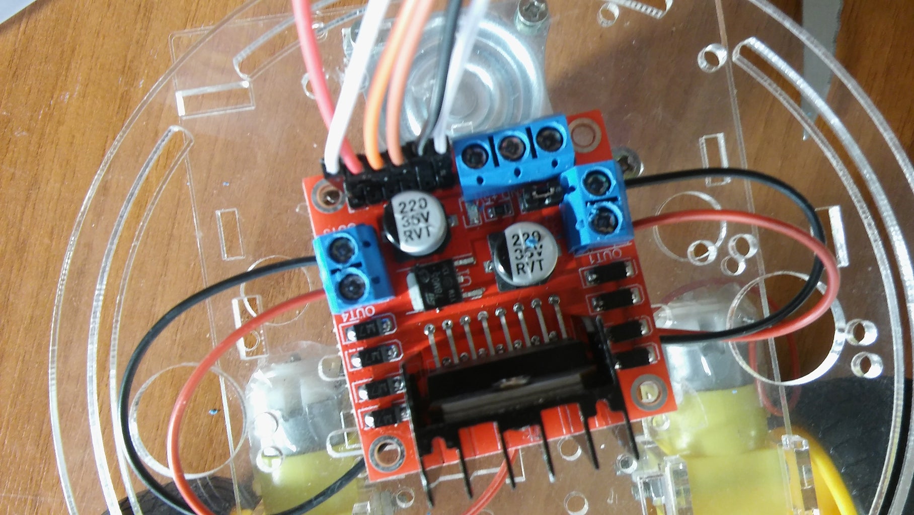
* first remove the jumper from the ENA and ENB pins in the motor driver
* connect both your motors to the OUTPUT A and OUTPUT B
* connect ENA to pin number 9 and ENB to pin numer 3
* connect pins IN1 IN2 IN3 IN4 to pins number 7 6 5 4 as shown in the pictures
* connect you battery to the module and make sure to connect the module GND with the arduino GND
* note that if your gonna use 9v battery it may not work especially if it old or it been used before
so i highly recommend using AA batteries instead it work better with robots
Step 7: Final Connection


connect everything together and use hot glue gun or screws to put everything on the chassis
Step 8: The Android App


* i made the app using http://ai2.appinventor.mit.edu its very simple
* i made a few comments in the picture to help you building your own app
* the app include a (LISTPICKER _ Bluetooth client _ timer _ 6 bottoms that sending characters from 0 to 5 _ labels)
Attachments

Step 9: The Arduino Code
* i made everything clear in the code by writing comments and the code is very simple
* feel free to edit the code and inform me if you have upgrade or a better way.
/* define section */
//Motor driver setup L298N const int IN1 = 7; //connect IN1 in the motor driver to pin number 7 in arduino const int IN2 = 6; //connect IN2 in the motor driver to pin number 6 in arduino const int IN3 = 5; //connect IN3 in the motor driver to pin number 5 in arduino const int IN4 = 4; //connect IN4 in the motor driver to pin number 4 in arduino
/* this will allow you to control the speed of the motors */
const int ENA = 9; //connect IN1 in the motor driver to pin number 9 in arduino const int ENB = 3; //connect IN1 in the motor driver to pin number 3 in arduino
//***************************************************************************//
int command = 0;// int to store the data that we will receive from the bluetooth
/* define the pins for the ultrasonic sensor */
int trig = 11; /* connect trigger pin of Ultrasonic to pin number 11 */ int echo = 12; /* connect echo pin of Ultrasonic to pin number 12 *
* void setup section we are going to setup our pins to input or output */
void setup() { Serial.begin(9600); // opens serial port, sets data rate to 9600 bps // set motor driver`s pins to output pinMode (IN1, OUTPUT); pinMode (IN2, OUTPUT); pinMode (IN3, OUTPUT); pinMode (IN4, OUTPUT); pinMode (ENA, OUTPUT); pinMode (ENB, OUTPUT); //set trig pin as output and the echo pin as input for the ultrasonic sesor pinMode(trig, OUTPUT); pinMode(echo, INPUT); }
/*void loop section we are going to write our main program here*/
void loop() {
if (Serial.available() > 0) //check if the arduino is receiving data or not { command=Serial.read(); //set command integer value sama as the value that we will receive from the bluetooth NOT(we are going to send characters from 0 to 5 and each character will do a different job.
} if (command == '0')//if we receive a character 0 then both motors will move forward
{ // by setting IN1 and IN3 HIGH and IN2 and IN4 LOW both motors will move forward accoring to my connections and ENA and ENB to control the speed from 0 to 250 and this same as the following characters digitalWrite(IN1, LOW); digitalWrite(IN2, HIGH); digitalWrite(IN3, LOW); digitalWrite(IN4, HIGH); analogWrite(ENA, 50); analogWrite(ENB, 50); command=0; //set command value back to 0 } else if(command == '1') // moving backward { digitalWrite(IN1, HIGH); digitalWrite(IN2, LOW); digitalWrite(IN3, HIGH); digitalWrite(IN4, LOW); analogWrite(ENA, 50); analogWrite(ENB, 50); command=0; //set command value back to 0 } else if (command == '2') //moving left { digitalWrite(IN1, HIGH); digitalWrite(IN2, LOW); digitalWrite(IN3, LOW); digitalWrite(IN4, HIGH); analogWrite(ENA, 50); analogWrite(ENB, 50); command=0; //set command value back to 0 } else if (command == '3') //moving right { digitalWrite(IN1, LOW); digitalWrite(IN2, HIGH); digitalWrite(IN3, HIGH); digitalWrite(IN4, LOW); analogWrite(ENA, 50); analogWrite(ENB, 50); command=0; //set command value back to 0 } else if (command == '4') //stop the motors { digitalWrite(IN1, HIGH); digitalWrite(IN2, HIGH); digitalWrite(IN3, HIGH); digitalWrite(IN4, HIGH); command=0; //set command value back to 0 } else if (command == '5') {
long du = 0, ds = 0; // Transmitting pulse digitalWrite(trig, LOW); //set trig pin to high delayMicroseconds(10); //wait 2MS digitalWrite(trig, HIGH); //set trig pin to high to send pulse delayMicroseconds(10); //wait 10MS digitalWrite(trig, LOW);// Waiting for pulse du = pulseIn(echo, HIGH);// check for the pulse ds = du*0.034/2 ;// Calculating distance
//move the motors forward
digitalWrite(IN1, LOW); digitalWrite(IN2, HIGH); digitalWrite(IN3, LOW); digitalWrite(IN4, HIGH); analogWrite(ENA, 50); analogWrite(ENB, 50);
if (ds<=10) //if the space betwen the robot and the object less than 10 or 10 then turn right until the robot gets a space more than 10 { analogWrite(ENA, 50); analogWrite(ENB, 50); digitalWrite(IN1, HIGH); digitalWrite(IN2, LOW); digitalWrite(IN3, HIGH); digitalWrite(IN4, LOW); delay(1000); analogWrite(ENA, 50); analogWrite(ENB, 50); digitalWrite(IN1, LOW); digitalWrite(IN2, HIGH); digitalWrite(IN3, HIGH); digitalWrite(IN4, LOW); delay(1000); } command='5'; //here we will let the robot do the same job untill the we press stop bottom from mobile or press any bottom so we control it manualy }
}
// created by abdulrahman rijabo :)
Attachments
Step 10: Testing the Robot
unfortunately my batteries died and i couldn't test the robot using battery so i used 12V adapter
and everything works fine here is a short videos

Participated in the
Wireless Contest

Participated in the
Wheels Contest 2017


