Introduction: PIC Wireless Controller for RC Car
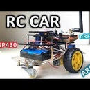
In this instructable we'll make a wireless controller with a PIC18F252 Microcontroller, an nRF24l01+ transceiver module and two analog joysticks. We'll program our MCU with the help of a PICKit3 progammer and the MPLAB X IDE. At the receiver side we'll use an RC car we had built in our previous instructables. Before you continue with this instructable, it's better that you check these first (PIC & nrf24l01+ Transmitter - DIY RC CAR):
https://www.instructables.com/PIC18F252-Microcontroller-NRF24L01-Wireless-Transm/
https://www.instructables.com/DIY-RC-CAR-MSP430-Arduino-Nrf24l01/
Supplies
Controller:
PIC18F252 Microcontroller from Microchip, Pickit3 Programmer, 8 MHz Crystal Oscillator (4 MHz or 16 MHz will be fine too), 2* 22pF capacitors, jumper cables, external adjustable power supply (optional), 2* nRF24l01+ module (for TX and RX), 2*100uF Capacitors (optional, between the 3.3V and ground for the nRF modules), 1* 10kOhm resistor (to be placed between the MCLR and VDD pins of PIC18F252), external 3.3V power supply (for the TX nRF24l01+), 2* 2-axis analog joysticks.
Receiver (RC CAR):
Arduino Nano (or Uno, it's up to you), nrf24l01+ transceiver module, jumper cables, 100 microFarad capacitor (optional), 2* 6V DC motors, 2 wheels, 1 caster wheel, 2* sg90 (or any other 5V driven servo), Robot Car chassis, 2*18650 Li-İon Batteries.
Step 1: HW Connections (Controller)
The connections for the controller is an extension of our previous transmitter project, so the instructions for the transmitter was:
-------------
In order to program the PIC18F252 with PICKIT3, you need to connect the devices as shown in the first picture. The connection is straightforward. The pin names of the PICKIT 3 are very descriptive. You'll have to connect a 10kOhm resistor between the MCLR and VDD pins, You'll connect the 8MHz crystal between the OSC1 and OSC2 pins (both will be connected to the ground over 22pF Capacitors). As soon as you make the connections you're ready to program your mcu. However it's better to make the nRF24l01+ connections at the same time and that is shown on the second picture,
As a summary, the connections between the PIC18F252 and the nRF24l01+ are:
RC0 -> MOSI, RC1 -> MISO, RC3 -> CSN, RC4 -> SCK, RC5 -> CE
In addition to this you have to use a reliable 3.3V Power supply for the nrf24 module, I used the 3.3V output of an MSP430 Launchpad.
------------------
What we're going to add to this setup above are the two analog joysticks:
The Vcc of both joysticks will be connected to the same power source connected to the Vdd and both grounds will be connected to the common ground. The X and Y axis outputs of the joysticks will be connected to the AN0,AN1, AN2 and AN3 pins of the MCU as can be seen in the picture.
Step 2: Connections for the RX (RC Car)
The connections are identical with the RC Car instructable:
3.3V pin on the Arduino --> Vcc on the nRF24 Module
GND pin on the Arduino --> GND on the nRF24 Module
D8 pin on the Arduino --> CE on the nRF24 Module
D13 pin on the Arduino --> SCK on the nRF24 Module
D7 pin on the Arduino --> CSN on the nRF24 Module
D11 pin on the Arduino --> MOSI on the nRF24 Module
D12 pin on the Arduino --> MISO on the nRF24 Module
VIN pin on the Arduino -->2*3.7V 18650 Li-ion battery pack
VIN of the L298N Motor Driver --> 2*3.7V 18650 Li-ion battery pack
D3 & D4 & D5 & D6 pin on the Arduino --> In1 & In2 & In3 & In4 on the L298N Motor Driver
D9 & D10 pins on the Arduino --> Signal pins of the Servos
Servos obtain their 5V supply from the 5V output of the L298N motor driver.
Enable pins on the L298N motor driver are connected via jumper cables (no PWM)
Capacitor optional as in the Transmitter.
Step 3: SW for Controller: MPLAB X IDE
For the controller, you can use my code in the following link:
https://github.com/selimg76/nrf24-PIC18F252/blob/main/main_PIC18f252_RC.c
In your MPLAB X IDE project, you should also include the nrf24.h file that I prepared:
https://github.com/selimg76/nrf24-PIC18F252/blob/main/nrf24.h
For detailed information abour programming PIC with PICKit3 and projects with nrf24l01+ you can check my following playlists:
https://youtube.com/playlist?list=PLbFgDf51ZkCFnMVlLYTHEWHmyUn5ofekg
https://youtube.com/playlist?list=PLbFgDf51ZkCHATIekg8ElpK-Gw-2Zyd8t
Step 4: SW for RC Car: Arduino IDE
For the RC Car (Receiver), you'll use my sketch in Arduino IDE, Here's the link:
https://github.com/selimg76/nrf24-PIC18F252/blob/main/rc_receiver_w_servo_no_pwm
If you want to use PWM for the DC motors, you'll have to use two more pwm capable pins.
I hope you liked this instructable. If you did, please like my instructable and consider subscribing to my YouTube Channel:
https://www.youtube.com/c/drselim
Thank you for your time and see you in another instructable!


