Introduction: PIPE BALL
Pipe Ball is a ball toss game. This is a very easy game to make.
This game has 16 pipes in 7 rows, with all pipes in the same row having the same point values.
The number of pipes in each row going in order front-to-back are 1, 2, 3, 4, 3, 2, 1.
In turn, these rows have point values of 5, 3, 2, 1, 4, 6, 8. Actually, you can number them anything you want … a logical value order would be 1, 2, 3, 4, 5, 6, 7 … with the front pipe scoring the least point, and point value getting progressively larger as the difficulty in landing a ball in a farther pipe increases.
The object of the game is to toss a tennis ball into one of the pipes to score points. ... The back row of pipes is the tallest and each row toward the front gets shorter. With the pipes being only 4″ in diameter and the tennis balls being 2.7″ in diameter, there isn’t a lot of room for error when you try to land the ball inside a pipe. Also, the bouncy nature of a tennis ball sends it flying left and right off of pipes when you miss the holes.
This particular game allows the thrower 10 tennis balls. The thrower throws all the balls until they all land in the pipes, with missed balls rolling back into the Ball Box in front of the game, where the thrower can continue throwing such balls.
When a ball lands in a pipe, it falls into the Ball Router Box directly below a pipe where it is routed into a specific ball channel in the Ball Channel Box directly below the Ball Router Box. Then the ball rolls to the front of the game in their assigned ball channel whose point values corresponds to the row of pipes into which the ball landed. When all balls have landed in pipes, the point values for each ball in their respective ball channels is manually added up. With multiple throwers, the thrower scoring the highest points wins.
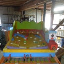
View of the finished Pipe Ball game is shown above.
Supplies
THE MATERIALS :
The materials needed for this particular project were as follows :
(2) 1 lb. box of 3” #9 wood screws
(1) tube wood glue
(3) ½” x 4 x 8 Birch, Maple, Oak or sanded Pine plywood
(1) ¾” x 4 x 8 Birch, Maple, Oak or sanded Pine plywood
(14) 2x4x8 boards
(1) 1x6x8 board
(2) 4” x 10’ PVC pipe
(1) roll 24” wire or mesh to cover an approx. 15’ length
(7) Pints of different color paints (semi-gloss)
(2) 5” fixes casters
(4) 5” free floating lockable casters
(10) Tennis Balls
TOOLS NEEDED :
Hand Level ... Square – Small ... Hammer ... Pliers
Pipe Clamps ... Hand Chisels ... Sander ... Paint Roller
Paint Brushes ... Stapler (¾” staples) ... Wire Snips
Jig Saw ... Miter Saw ... Circular Saw ... Table Saw
Router ... Tape Measure ... Straight Edge 3’ ruler
Angle Ruler ... Drill ... Drill Bits : various sizes
Hole Saw : 4+ ½” (can substitute cutting with jig saw)
Hole Saw : 4” (can substitute cutting with jig saw)
Step 1: BALL CHANNEL BOX :
60” L x 25+ ½” W x ¾” Thick x 4” H spacers
The Ball Channel Box contains 7 ball channels assigned to all pipes in each of the 7 pipe rows.
When a ball lands into a pipe, it drops into the Ball Router Box (immediately below the pipes and above the Ball Channel Box), and is directed to the ball channel in the Ball Channel Box with the same point values as the pipe. The ball then rolls forward in the assigned ball channel and appears in the channel Viewing section where the thrower can view the balls and count their point values.
The Ball Channel Box is a very simple construction of 6 channel Spacers ½” W x 4” High for 7 channels, which are glued and nailed onto a panel 60” L x 25+ ½” W x ¾” Thick. The channels run the entire length of the Channel Box.
¾ x 5+ ¼” High plywood is installed on both outer sides of the base ¾” panel to finish enclosing the Ball Channel Box.
A 13+ ½” exposed section of the ball channels in the front is used by the thrower to view and count the number of balls in each ball channel in order to total up their points.
Spacers ½” x 12+ ½” L are laid on top of the Channel Spacers in the front to:
1) be flush with the side panels, and
2) be flush with the 10” W x ½” green front pane used as the Ball Box (will be framed later) into which missed balls will roll and also for ball storage, and
3) to accent the top of the ball channels in red.
An 8” High x ½ “Thick green riser panel then blocks the view of the 7” High Ball Router Box and rises 1” above it to eventually be flush with the ½” Ball Router Box panel + the ½” Pipe Top Panel.
The 36” Ball Router Box and the Pipe Top Panel reside approx.. 30” back from the front of the Ball Channel Box (channels are 24” back + the 6” extension discussed next) in order to expose the Ball Channel Viewer, the Ball Box, and the # extension to the thrower.
Step 2:
A front extension piece was put on for cosmetic purposes.
The number panel is 4+ ½” W x 25+ ½” L … and the top piece is 1+ ½” W … equals a 6” extension in front of the Ball Channel Box.
3+ ½” number labels were inserted, and these match the pipe point values.
When the balls land in the related pipe numbers, the balls roll down to the front of the game where they can be seen and their point values added up.
Step 3: BALL ROUTER BOX :
7” High (6” Router Box + ½” bottom panel + ½” top panel) x 36” L x 25+ ½” W
The Pipe Top Panel must be made before the Ball Router Box, otherwise it would be unknown where the pipes would be located to route them. It is laid on top of the Ball Router Box bottom panel, and the pipe holes are outlined for reference purposes where the ball will fall.
The Ball Router Box has a ball channel system of its own …
it routs or channels the balls of specific pipes into specific channels in the Ball Channel Box … that’s its job!
Ex: there are four # 1 pipes … they are each routed into the same Value Point ‘1’ … the 1st channel on the left.
All pipes on any 1 row are routed into the same ball channel assigned for them in the Ball Channel Box.
Aerial view of the Ball Router Box.
All channels are sloped 3+ ½”, where all balls in a channel only roll into 1 hole which drops into the assigned channel in the Ball Channel Box below it.
The bottom panel of the Ball Router Box is in 2 parts :
1) The first 4 channels are sloped to the Left side of the game, while
2) the 3 channels on the right are sloped to the Right side.
Stops are placed at each hole to prevent the ball(s) from rolling any further, and fall into the hole.
The channel to the far left and the channel to the far right are not used..
Step 4:
Picture # 1 : Close-up of the first 4 channels
Picture # 2 : Close-up view of the last 3 channels
Picture # 3 : Close-up view of channels 3-thru-6 … channels 3 and 4 slope to the left, and channels 5 and 6 slope to the right.
When determining where to cut the holes in the bottom panel of the Ball Router Box, note 2 outlines are done on the panel :
1) Channels (in red) aligned with the Ball Channel Box were drawn
2) Pipe outer dimensions were drawn … this was traced from the Top Panel which was laid out and cut before the Ball Router Box was set-up … this identified where the balls were to drop out of the pipes.
Seeing where the balls will fall and the channels they were assigned to made it easy as to where to cut the holes.
Step 5:
Picture # 1 : Left Side view from the back … note how 1st 4 ball rows in front are slanted down, while last 3 ball rows are slanted up.
Picture # 2 : Right Side view from the back … note how 1st 4 ball rows are slanted up, while last 3 ball rows are slanted down.
Note how the panels are angled using scrap pieces of plywood.
Angled spacer boards are cut to accommodate the slant.
Step 6: BALL ROUTER BOX PANEL :
The Pipe Top Panel (picture # 2) is laid on top of the Ball Router Box top panel (picture # 1), the pipes are inserted into the Pipe Top Panel (pipe outer diameters), and the inner pipe diameters are outlined and holes cut on the Ball Router Box top panel. This will allow the pipes to go through the Pipe Top Panel and just sit on the Ball Router Box top panel without falling through it … thus the balls can fall into the pipe and directly into the ball channels of the Ball Router Box and roll down a hole into the assigned ball channels in the Ball Channel Box.
Step 7:
(Pic # 1) View of the Ball Router Box top panel placed on top of the Ball Router Box. Verify the ball holes are aligned with the channels.
(Pic # 2) Close-up view of the Ball Router Box top panel placed on top of its ball channels.
(Pic # 3) Close-up view of the Ball Router Box top panel placed on top of its ball channels.
(Pic # 4) Close-up view of the Ball Router Box top panel placed on top of its ball channels.
(Pic # 5) Close-up view of the Ball Router Box top panel placed on top of its ball channels.
Step 8: PIPE TOP PANEL :
36” L x 25+ ½” W x ½” Thick
The Pipe Top Panel was designed to hold 16 pipes in 7 rows. With rows starting from the bottom, the number of pipes they handle are 1, 2, 3, 4, 3, 2, 1. The outer dimensions of the 4” pipes (which is 4+ ½ “) is outlined and cut.
The Ball Channel Box must be made before the Ball Router Box in order for the Ball Router Box to know into what ball channels the balls should be routed to … while the Pipe Top Panel must be made before the Ball Router Box, otherwise it would be unknown where the pipes would be located to route them.
Step 9:
The Pipe Top Panel placed on top of the Ball Router Box top panel … it is free-floating … it is not secured.
When the pipes are placed through the Pipe Top Panel, they will sit on top of the Ball Router Box top panel.
There is no need to permanently attach the Pipe Top Panel, as the game Frame will hold it in place.
Also the weight of the pipes themselves will generally not move, particularly since there are 16 pipes huddled together
Step 10: THE PIPES :
16 Pipes : 4” Inner Diameter / 4+ ½ Outer Diameter
Bevel 22+ ½°
The pipes are 4” PVC (4” inner diameters with outside diameters of 4+ ½”) angled at 22+ 1/2°
Two 10’ pipes are needed to cut the following lengths :
1 – 5”; 2 - 6+ ¾”, 3 - 8 ⅜ “ ; 4 - 10⅛”; 3 - 11+ ¾”; 2 - 13+⅜”; 1 - 15” = approx.. 13+ ½ feet … extra length is needed for fine tuning and mistakes.
The pipes need not be anchored in any way when placed into the Pipe Top Panel, since the weight of the pipes themselves will generally not move, particularly since there are 16 pipes huddled together.
Step 11:
(Pic # 1) Here the pipes are inserted into the Pipe Top Panel.
Note how snug the pipes are around the Pipe Top Panel, which is a result of exact measurement of their 4+ ½” diameters.
Sitting only ½” into the Pipe Top Panel, they are immediately sitting on the Ball Router Box top panel’s smaller 4” diameter measurements, with no space between these two panels … the pipes are still heavy enough to withstand the pounding of tennis balls without moving significantly.
(Pic # 2) The back of one pipe must be exactly level with the front of the pipe behind it … hence, extra pipe needed to get it right
Step 12: THE FRAME :
29+ ½” W x 48” L x 25” High Base
35+ ½” W with double outer frame 2x4 supports
The Frame Length of 48” is much shorter than the 66” Length of the Ball Channel Box (60” box length + 6” number extension) … this is due to the Ball Channel Box Viewer and Ball Box sections intentionally extending another 18” beyond the frame for both functional and artistic effect, and to keep the thrower a little farther back from the pipes.
Step 13:
(Pic # 1) View of the interior of the Frame. The base Frame is only 25” High to the level of the bare 2x4’s. Everything else sits on these.
Side panels are 12” H in front, rising to 36” High in back.
Back panel is 26” W x 36” High.
(Pic # 2) Right side view of Frame. The 3 frame supports are 35+ ½”, 48”, and 60” High without the casters.
(Pic # 3) Back view of Frame.
(Pic # 4) Left side view of Frame.
Step 14:
(Pic # 1) The RISE of the Pipe Pall game to facilitate ball roll is controlled by Six (6) 1” x 6” x 25” boards. 3 in back, 2 in middle, 1 in front … when the Ball Channel Box sits on these, it provides a good pitch for the game, thus allowing the balls to roll to the front of the game in the ball channels.
(Pic # 2) Here is the Ball Channel Box, the Ball Router Box, and the Pipe Top Panel about to slide into the Frame.
Step 15:
(Pic # 1) The entire Box assembly is tilted and slid into the Frame, and now sits on top of the 6 riser boards in the back of the Frame. Everything is now snug into the Frame.
(Pic # 2) 2 boards serve as ball stops for the Ball Box.
It also prevents the entire unit from sliding out of the Frame.
The entire unit just sits on the Frame … it is not anchored in any way. If desired, a couple screws into the side will suffice.
Step 16: THE CAGE :
30” W x 60” Long x 16” H
Balls bounce, and tennis balls bounce all over the place more than others … and this game uses Tennis Balls.
Therefore some type of Ball Cage is necessary.
Height dimensions for this Cage was 16” all around, with a 20” L front drop over the balls.
Independent framing in ‘green’ was installed to anchor the cage netting, which is a fish type netting … nothing stronger is really needed. White molding strips help support the netting and are also cosmetic for effect.
The rear and front side frames were extended down to the bottom of the Ball Channel Box for stability.
Step 17: THE FINISH :
Play Ball !


