Introduction: PIR Controlled 433MHz Switch Without a Micro Controller


A PIR motion detector sensor is used to trigger sending off or on commands to a 433MHz switch. This is quite easily done using a micro controller, but this project will not use a micro controller (other than for some initial steps).
Hence this project should be a strong candidate for the Most Useless Project Contest, if such a contest existed.
The idea is to store the codes for turning the switch on and off in an EEPROM, The PIR sensor should trigger transmitting the code to the switch via a 433MHz transmitter.
WARNING: Make sure that usage of 433MHz transmitters are legal in your country and region!
The radio controlled switch
Radio controlled switch is a wall plug switch that can be controlled by a remote control using 433MHz radio signal. They are highly available, and can be quite cheap. Mine is bought here. Also, there exist switches that react on movements using PIR sensor. A PIR sensor controlled 433MHz transmitter combines these, and the PIR sensor can be away from the wall plug.
How it works
The transmitter sends high and low signals with duration determined by the protocol in use. A 555 timer will be used to generate the clock signals required for this. Each bit of the codes will be stored in the EEPROM, A parallel EEPROM will be used, where the addresses of the data are accessed using a binary counter, and the bits of each byte are shifted to the transmitter with a shift register. In addition some control circuits are needed to start and stop the transmission, and to keep track of the loading of data from the EEPROM to the shift register.
The wall plug receives the signal, and turns power on or off.
Step 1: Obtaining the Codes to Transmit


To get the transmission code, the Arduino example sketch which is found under rcswitch>ReceiveDemo_advanced, can be used. If the rcswitch library is not installed, it can be installed from the library manager.
Connect a 433Mhz receiver to interrupt pin #0 (pin 2 on the Mega or Uno, pin 3 on the Micro) and to 5V and ground. When the sketch is running, press the on button on the remote control, and read the Serial output. Press the button several times, and see if there is a number that comes up more frequent than others. For me, I found that 38909585 frequently showed up.
Decimal: 38909585 (28Bit) Binary: 0010010100011011011010010001
Tri-State: not applicable PulseLength: 499 microseconds Protocol: 2
Similarly 39916949 was frequent for off-code
The codes can be tested with the SendDemo, also from rc-switch example. The sketch will need to be edited based on the result of the ReciveDemo above.
Connect the transmitter's data pin to pin5 on the Arduino, and connect 5V and ground.
Remove or comment out/in the relevant lines for the findings from ReceiveDemo. For my switch, I ended up with:
#include
RCSwitch mySwitch;
void setup() {
  Serial.begin(9600);
  // Transmitter is connected to Arduino Pin #5
  mySwitch.enableTransmit(5);
  // Optional set pulse length.
  mySwitch.setPulseLength(499);
  // Optional set protocol (default is 1, will work for most outlets)
  mySwitch.setProtocol(2);
}

void loop() {
  mySwitch.send(39916949, 28);
  delay(1000);
  mySwitch.send(38909585, 28);
  delay(1000);
  delay(20000);
}
However, that did not work. It appears that the pulse length found by the receive demo is too large. Also, the pulse length needs to be set after the protocol number. Finally, this worked for me:
#include
RCSwitch mySwitch;
void setup() {
  Serial.begin(9600);
  // Transmitter is connected to Arduino Pin #5
  mySwitch.enableTransmit(5);
  // Optional set protocol (default is 1, will work for most outlets)
  mySwitch.setProtocol(2);
  // Optional set pulse length.
  mySwitch.setPulseLength(450);
}

void loop() {
  mySwitch.send(39916949, 28);
  delay(1000);
  mySwitch.send(38909585, 28);
  delay(20000);
}
The switch now repeatedly turned on and off.
From RCswitch.cpp, protocol 2 is described by
default pulse length,  sync bit    0-bit      1-bit   inverted
{      650,           { 1, 10 }, { 1,  2 }, { 2,  1 }, false }
This means, that to send a code, there should first be transmitted 1 pulse length signal high, then 10 pulse lengths signal low to sync, and then for each bit in the code, 1 pulse length of low, then 2 pulse lengths of high, if the bit is 0, else 2 pulse lengths high an then 1 pulse length low.
If inverted were true, then high and low should be exchanged, but it is not.
Hence, for the code decimal 39916949, binary: 0010011000010001010110010101, the transmitted sequence should be
   Sync      0   0   1   0   0   1   1   0   0   0   0   0  ...
HLLLLLLLLLL HLL HLL HHL HLL HLL HHL HHL HLL HLL HLL HLL HHL ...
The pulse length will be 450, as was found by trial and error using the SendDemo switch.
Step 2: Programming the EEPROM With the Codes

The EEPROM used is a AT28C64B 64 KB parallel. Its data sheet can be found here.
An Arduino Mega is used to program the codes into the EEPROM. This is because more pins are needed, than is available on an UNO or Micro. If they are to be used, port replicators will be needed, and the sketch would be more complicated.
The code is 28 bit, where each bit is represented by 3 pulses, high or low. In addition, a sync code is transmitted before the on or off code, with 11 pulses. These numbers may depend on the brand and type of the switch.
With the numbers above, 3x28 + 11 = 95 pulses is transmitted to send a code, which may be stored as 12 bytes in the EEPROM. To have a more robust switching, the code will be re-transmitted several times. To send five times 60 bytes is needed for each code. 64 bytes in the EEPROM will be used for each of the two codes.
Addresses 0 to 63 (or 0 to 0x3F) for the off-code and addresses 64 to 127 (or 0x40 to 0x7F) for the on code.
To address the 128 first bytes of the EEPROM, 7 pins (A0 - A6) will be needed. The sketch to be used for programming, can access also pin A7. The other address pins, A8 to A 12, should be tied to ground.
PORTA of the Arduino Mega is used to access the address pins A0 to A7. PORTA uses pins 22-29. So pin 22 on the Mega should be connected to pin A0 on the AT28C64B, pin 23 to A1 and so on, pin 29 to A7.
To enter or read data from the the address specified by the address pins, the I/O pins I/O0 to I/O7 on the AT28C64B are used. These should be connected to PORTC, which are pins 37 to 30 on the Mega (note that they are numbered backwards). So pin 37 on the Mega should be connected to pin I/O0 on the EEPROM, pin 36 to I/O1 and so on, pin 30 to I/O7.
In addition pin 2 on the Mega should be connected to pin CE on the EEPROM, pin 3 to OE, and pin 4 to WE.
For testing purpose, the 433MHz transmitter should also be connected: GND to ground, VCC to 5V, and DATA (or ATAD as said on some of them) to pin 5 on the Mega.
With VCC connected to 5V, and GND to ground, programming the EEPROM can be done with the sketch below.
You will need to enter the codes and protocol that was obtained for your switch in the previous step.
#include <Arduino.h>

constexpr bool dry_run    {false};
constexpr bool do_program {true};

// codes
constexpr uint32_t on_code  {38909585};
constexpr uint32_t off_code {39916949};

// protocol
constexpr int pulse_length   {450};  //RCswitch reports too high value
constexpr uint8_t on_bit[]   {2, 1};
constexpr uint8_t off_bit[]  {1, 2};
constexpr uint8_t sync_bit[] {1, 10};
constexpr int code_length    {28};

constexpr uint8_t off_address {0x00};
constexpr uint8_t on_address  {0x40};

constexpr int transmit_pin {5};

constexpr int serial_speed {9600};
constexpr int on_off_delay {1000};

// ------- most configuration above here -----------

constexpr uint8_t ones(int n) {
  return n <= 1 ? 1 : (1 << (n-1)) | ones(n-1);
}

template <typename T>
constexpr T diff(T a, T b) {
  return a > b ? a - b : b - a;
}

constexpr int npulse {on_bit[0] + on_bit[1]};
constexpr int nsync  {sync_bit[0] + sync_bit[1]};

constexpr int code_size  {nsync + code_length * npulse};
constexpr int code_bytes {(code_size + 7) / 8};
constexpr int repeat     {diff(on_address, off_address) / code_bytes};

constexpr uint8_t off  {ones(off_bit[0])};
constexpr uint8_t on   {ones(on_bit[0])};
constexpr uint8_t sync {ones(sync_bit[0])};

// ------------------------------------------------------------------------
// Arduino Mega parallel EEPROM programmer
// can program 256 entries (8 bit addresses)

// PORTA for address pins 22-29
// PORTC for data pins 37-30

// DRY_RUN can be used for storng data in Arduino memory
// instead of an actual EEPROM.


template <bool DRY_RUN = false>
class Eeprom {
  static constexpr int CE{2};
  static constexpr int OE{3};
  static constexpr int WE{4};

  uint8_t eeprom[DRY_RUN ? 256 : 1];

#ifndef ARDUINO_AVR_MEGA2560
  static_assert(DRY_RUN, "Arduino Mega needed if not dry_run");
  int DDRA, PORTA;
#endif

public:
  void begin() {
    pinMode(CE, OUTPUT);
    pinMode(WE, OUTPUT);
    pinMode(OE, OUTPUT);
    digitalWrite(OE, HIGH);
    digitalWrite(WE, HIGH);
    digitalWrite(CE, HIGH);
    DDRC = 0x00;
    DDRA = 0xff;
    PORTA = 0x00;
  }

  void writeByte(uint8_t data,
                 uint8_t address) {
    digitalWrite(OE, HIGH);
    digitalWrite(WE, HIGH);
    digitalWrite(CE, LOW);
    DDRC = 0xFF;
    PORTC = data;
    PORTA = address;
    digitalWrite(WE, LOW);
    delayMicroseconds(1);
    digitalWrite(WE, HIGH);
    digitalWrite(CE, HIGH);
  }

  uint8_t readByte(uint8_t address) {
    digitalWrite(OE, HIGH);
    digitalWrite(WE, HIGH);
    digitalWrite(CE, LOW);
    DDRC= 0x00;
    PORTA = address;
    digitalWrite(OE, LOW);
    delayMicroseconds(1);
    uint8_t data {PINC};
    digitalWrite(OE, HIGH);
    digitalWrite(CE, HIGH);
    return data;
  }
};

// Alternative versions for dry run
template<>
void Eeprom<true>::begin() {}

template<>
void Eeprom<true>::writeByte(uint8_t data,
                             uint8_t address) {
  eeprom[address] = data;
}

template <>
uint8_t Eeprom<true>::readByte(uint8_t address) {
  return eeprom[address];
}

Eeprom<dry_run> eeprom;

// ------------------------------------------------------------------------

class Reader {
  int32_t bit_count {0};
  uint8_t bits {0};
  uint8_t address;
public:
  explicit Reader(uint8_t start_address)
    : address(start_address) {}

  uint8_t getAddress() const {
    return address;
  }

  bool readBit() {
    if (bit_count++ % 8 == 0) {
      bits = eeprom.readByte(address++);
      bit_count = 1;
    }
    bool bit = bits & 1;
    bits >>= 1;
    return bit;
  }

  void skipSync() {
    for (int b {0}; b < nsync; ++b) {
      (void) readBit();
    }
  }

  bool readCodeBit() {
    uint8_t code_bit {0};
    for (int b {0}; b < npulse; ++b) {
      if (readBit()) {
        code_bit |= (1 << b);
      }
    }
    if (code_bit != on && code_bit != off) {
      Serial.print("Illegal code bit: ");
      Serial.println(code_bit, HEX);
    }
    return code_bit == on;
  }

  uint32_t readCode() {
    skipSync();
    uint32_t code {0};
    for (auto c {code_length}; c--;) {
      if (readCodeBit()) {
        code |= (1L << c);
      }
    }
    return code;
  }
};

class Writer {
  int32_t bit_count {0};
  uint8_t bits {0};
  uint8_t address;
public:
  explicit Writer(uint8_t start_address)
    : address(start_address) {}

  ~Writer() {
    if (bit_count != 0) {
      eeprom.writeByte(bits, address);
    }
  }

  uint8_t getAddress() const {
    return bit_count == 0 ? address : address + 1;
  }

  void writeBit(bool bit) {
    if (bit) {
      bits |= (1 << bit_count);
    }
    if (++bit_count == 8) {
      eeprom.writeByte(bits, address++);
      bits = bit_count = 0;
    }
  }

  void writeCodeBit(bool bit) {
    uint8_t code_bit {bit ? on : off};
    for (int b {0}; b < npulse; ++b) {
      writeBit(code_bit & (1 << b));
    }
  }

  void writeSync() {
    for (int b {0}; b < nsync; ++b) {
      writeBit(sync & (1 << b));
    }
  }

  void writeCode(uint32_t code) {
    writeSync();
    for (auto c {code_length}; c--;) {
      writeCodeBit(code & (1L << c));
    }
  }
};

// ------------------------------------------------------------------------

bool verifyEeprom(uint32_t expected,
                  uint8_t address) {
  Reader reader(address);
  for (int r {0}; r < repeat; ++r) {
    uint32_t code {reader.readCode()};
    Serial.println(code, HEX);
    if (code != expected) {
      Serial.println("Code verification failed");
      return false;
    }
  }
  Serial.println(reader.getAddress(), HEX);
  return true;
}

void writeEeprom(uint32_t code,
                 uint8_t address) {
  Writer writer(address);
  Serial.println(code, HEX);
  for (int r {0}; r < repeat; ++r) {
    writer.writeCode(code);
  }
  Serial.println(writer.getAddress(), HEX);
}

void setup() {
  Serial.begin(serial_speed);
  pinMode(transmit_pin, OUTPUT);
  eeprom.begin();

  if (!dry_run && !do_program) {
    return;
  }

  // Write the codes to the EEPROM
  Serial.println("clearing");
  for (int i {0}; i <= 0xff; ++i) {
    eeprom.writeByte(0, i);
  }

  Serial.println("writing");
  writeEeprom(off_code, off_address);
  writeEeprom(on_code, on_address);

  Serial.println("verifying");
  if (!verifyEeprom(off_code, off_address) ||
      !verifyEeprom(on_code, on_address)) {
    for (;;) {}
  }
}

void sendCode(uint8_t address,
              uint8_t nbytes) {
  // Sends the code stored in the EEPROM to the transmitter
  for (uint8_t n {0}; n < nbytes; ++n) {
    uint8_t bits {eeprom.readByte(address++)};
    for (uint8_t b {0}; b < 8; ++b) {
      digitalWrite(transmit_pin, bits & 1 ? HIGH : LOW);
      delayMicroseconds(pulse_length);
      bits >>= 1;
    }
  }
}

void loop() {
  constexpr uint8_t addresses[] {
    off_address, on_address, off_address, on_address};

  for (auto adr : addresses) {
    Serial.println(adr == on_address ? "on" : "off");
    sendCode(adr, diff(on_address, off_address));
    delay(on_off_delay);
  }
  for(;;) {}
}
The sketch can also be found here.
If everything is OK, then the EEPROM is programmed, and the codes are then read from the EEPROM and sent to the transmitter, turning the switch off and on twice.
When the EEPROM is programmed, there will be no more need for the Arduino.
Step 3: From EEPROM to Transmitter


The codes will be stored in an EEPROM, and shifted out to the transmitter via a shift register.
For each address its 8 bit of data are loaded into a shift register, and then shifted out to the transmitter, one bit per pulse length.
Two 74HC194 four bit shift registers, cascaded to handle 8 bits of data, are used. These shift registers are capable of loading four bits of data in parallel, and shift them out in either end. The data sheet can be found here.
At every rising edge on the clock pin CP, data is shifted to the right, if S0 is high and S1 is low. If, however both are high, parallel load is performed in stead.
The data is loaded from the EEPROM by connecting I/O0 to I/O3 at the AT28C64B to pins D0 to D3 on the first 74HC194, and pins I/O4 to I/O7 to pins D0 to D3 on the second. These are the yellow wires in the Fritzing image.
The last output pin, Q3 of the second shift register will go to the transmitter (also yellow).
To cascade the two shift registers, Q3 of the first shift register should be connected to the SR pin of the second, so that data can be shifted from the first to the second. The clock pins CP, the master reset pins MR and the control pins S1, should be connected between the two shift registers, so that they will operate in sync (CP - CP white, MR - MR blue, S1 - S1 grey). On both shift registers S0 is tied to VCC, and DSL is tied to ground. On the first shift register, DSR is also tied to ground. When the system is idle, MR will be kept low, so that nothing is transmitted.
Just before the input clock CP on the shift registers goes high for the parallel load, the EEPROM must have the data ready in the I/O pins.
Data is made ready by setting the address pins A0 to A12 to the wanted address, and then bringing the chip enable (CE) and output enable (OE) pins low. The eight bits of data in the set address, will then be present on the pins I/O0 to I/O7 for the shift registers to load. After the load has finished, the OE and CE pins can be pulled high again , and the next address can be set on the address pins.
To set the address, a 74HCT393 8-bit binary ripple counter, is used. This is a binary counter that consists of two 4-bit parts. The datasheet can be found here.
The 74HCT393 will count the addresses and set the address pins on the EEPROM. The total length of data that should be transmitter for each code will fit in 64 bytes, which can be addressed by 6 bits. The 7th bit can be used to select on or off code.
So from the binary counter, the output pins 1Q0 to 1Q3 and 2Q0 to 2Q1, are connected to the address pins A0 to A5, respectively, on the EEPROM. A6 is used to select on or off code, and will be connected to the output of the PIR sensor. The other address pins, A7 to A12 will not be used, and should be tied to ground.
The binary counter will count, and hence set a new address, at every falling edge of the signal on the clock pin 1CP. To be able to count beyond four bits, the output pin 1Q3 should be connected to to the clock pin of the second part 2CP (white). The clock pin 1CP will be pulled low once between each load to the shift register, to have the address set for the load. When the counter has counted through all the 64 addresses, pin 2Q2 goes high (next count) and signals that all is done. The reset pins 1MR and 2MR will be kept high when the system is idle, to ensure that counting will start again from 0.
Step 4: Start and Stop


The PIR sensor output signal goes high when motion is detected, and stays high until no motion is detected during a timeout period. The transmitter should start sending an on-signal when the sensor signal goes from low to high, and an off signal when the signal goes from high to low. The transmission should stop when the signal is fully sent.
S-R latch
An SR latch (set/reset latch) will be used to achieve this. An SR latch has two inputs (S and R) and two outputs (Q and /Q, where /Q is the inverse of Q). When S goes high, when R is low, the latch will be set and Q becomes high. Q will stay high if S goes low again. Hence it can be set by a high pulse on S. When S is low while R goes high, the latch will be reset, and Q will be low.
Two NOR gates can be cross coupled as in the picture above, to build an SR latch.
The truth table for the NOR gates SR latch looks like:
|  S  |  R  |  Q  | /Q  |  Operation |
|_____|_____|_____|_____|____________|
|  0  |  0  |  Q  | /Q  | No change  |
|  1  |  0  |  1  |  0  | Set        |
|  0  |  1  |  0  |  1  | Reset      |
|  1  |  1  |  X  |  X  | Illegal    |
When the latch is set, the master reset pins of the counters and shift registers will be off, and they will count and shift. The Q output is connected to the active low /MR of the shift registers, and the /Q is connected to the MR of the counter.
Two of the four NOR gates of a 74HC7002 quad NOR chip is used to build the latch. Its datasheet can be found here. The input 1B is connected to the output 2Y, and the input 2A is connected to the output 1Y. Then the input 1A will bet the S input, the input 2B wiil be the R input, output 2Y will be the Q output and 1Y the /Q output.
The connections are described in the picture above by Napalm Llama [CC BY (https://creativecommons.org/licenses/by/2.0)]
RC integrator
The latch should set on both the rising edge and the falling edge of the PIR sensor output. A double edge detector can be made from an XOR gate and an RC integrator.
An RC integrator consist of a capacitor and a resistor. The input goes through the resistor to the output, which is connected to ground through the capacitor.
          resistor         capacitor
Input -----\/\/\/\-----o-----||------ Ground
                     Output
The current trough the resistor will equal the current through the capacitor.
The current through a capacitor is proportional to the change in voltage over the capacitor:
Ic = C dVc/dt, where C is the capacitance of the capacitor.
The current trough the resistor is directly proportional to the voltage over the resistor:
Ir = Vr/R, where R is the resistance of the resistor.
Ic - Ir = CdVc/dt - Vr/R = Cdv/dt - (Vi - Vc)/R = CdVc/dt + Vc/R - Vi/R = 0
which is a differential equation for the output voltage (the voltage over the capacitor).
This has the solution Vc(t) = Vi + (Vc(0) -Vi) exp(-t/RC)
If, at t=0, the initial voltage Vc(0) over the capacitor has some value different from Vi, Vc will rise or fall exponentially with time, towards Vi.
The output of the XOR gate is Vcc when its two inputs are different, and 0 it they are equal. Or more specifically, for the 74AC86, Vcc if one input is greater than 0.7Vcc and one is less than 0.3Vcc, 0 if both are greater than 0.7Vcc or less than 0.3Vcc. Otherwise, it is not specified. The datasheet for the 74AC86 can be found here.
If Vi and Vc is connected to each input of the XOR gate, the output will be Vcc when Vi changes, and 0 after a while, when Vc catches up.
If the solution is written as: exp(-t / RC) = (Vi - Vc(t)) / (Vi - Vc(0)), one can get the time for Vc(t) to reach a value Vc:
t = -RC log((Vi - Vc) / (Vi - Vc(0)))
For the rising edge input, Vc(0) = 0, and Vi = Vcc, the time for Vc to reach 0.7Vcc (XOR(Vi, Vc) = 0) is
t = -RC log(Vcc - 0.7Vcc/ Vcc) = -RC log(0.3) = 1.2RC
and the time to reach 0.3Vcc (XOR(Vi, Vcc) = Vcc is -lRC log(0.7) = 0.36RC.
Hence the rising edge input gives a positive output pulse of the XOR gate with duration minimum 0.36RC and maximum 1.2RC. And so does the falling edge.
The output pulse from the XOR gate set the SR latch. RC should be chosen so that the duration of the pulse is less than the time until it is reset, to avoid the illegal state.
If R = 10kΩ, and C = 0.1µF, the pulse will be less than 3.6ms, which is about the time used to transmit only three bits of the code, so these values will do.
So a pulse is sent to the S input when the PIR output goes from high to low and also from low to high, to set the latch,
Reset of the ICs
To reset the latch, when the address counter has counted through its 64 addresses that holds the transmission code, pin 2Q2 of the binary counter goes high (to continue counting). This will be the signal that transmission is done. The signal will reset the latch, and the counter will master reset, which brings the 2Q2 pin low again.
So a pulse is also sent to the R input when transmission is finished, to reset the latch. Since the PIR input stays high for several seconds when it is on, and will stay low for several seconds when it goes low, there is no chance for illegal state of the latch.
The 555 timer is enabled when the latch is set only, by connecting the active low /Reset pin to the Q output of the latch. The Q output is also connected to the active low /MR of the shift registers. The inverse output /Q of the latch is connected to the MR of the address counter, so it will count when the latch is set, and reset the counters to zero when the latch is reset.
Step 5: Timing and Counting

A SE555 timer in astable mode gets things going. This produces a clock signal, that in turn will drive the other components. Its data sheet can be found here.
The 555 timer is connected as in the illustration above (By jjbeard - Own drawing, made in Inkscape 0.43, Public Domain, https://commons.wikimedia.org/w/index.php?curid=8...).
Counting shifts and loads
For every eight bit that is shifted out to the transmitter, a new byte of data is loaded and data from that address of the EEPROM is loaded to the shift register.
Another 74HCT393 8 bit binary counter is used to achieve this.
This counter (using only the four bits of part 2), counts on every falling edge of the clock signal from the output of the 555 timer connected to pin 2CP. On every rising edge of 2Q0, the output signal of the transmitter should be set high or low. The signal is the rightmost bit of shift register. So the first output pin of the counter, 2Q0 should be connected to the clock pins (CP) of both the shift registers (white).
To get the right frequency for the transmitter, R1 is 2kΩ, R2 is 680Ω, and the capacitor is 0.1µF. The frequency for the shift register, and hence the transmitter, will be half the frequency of the 555 timer.
The frequency of the timer is 1 / (0.693 × (R1+2R2) × C1), or 4.3kHz with the above values.
The fourth pin, 2Q3, will toggle every 8th count. This is connected to the clock pin, 1CP, of the address shift register. Hence a new address will be set after every 8th transmitted signal.
At the first clock pulse in the series of eight, the output shift registers should be loaded from the EEPROM, rather than shifted out. This is done by setting the OE pin of the EEPROM low, and the S0 and S1 pins of the shift registers high. Then, at the next clock pulse going high on the shift registers, data is loaded from the EEPROM into the shift register, rather than being shifted out to the right, as when S0 is high and S1 is low. Since the S0 pins should always be high, they are tied to 5V. S1 is set high when 2Q1, 2Q2, and 2Q3 are all low, so it will be high when the clock of the shift register goes high (2Q0).
If the address counter is A, and the shift counter is B:
555  01010101010101010101010101010101010101010101010101010101010101010101010101
B2Q0 00110011001100110011001100110011001100110011001100110011001100110011001100
B2Q1 00001111000011110000111100001111000011110000111100001111000011110000111100
B2Q2 00000000111111110000000011111111000000001111111100000000111111110000000011
B2Q3 00000000000000001111111111111111000000000000000011111111111111110000000000
SR     L   S   S   S   S   S   S   S   L   S   S   S   S   S   S   S   L   S
S1   11110000000000000000000000000000111100000000000000000000000000001111000000
OE   00001111111111111111111111111111000011111111111111111111111111110000111111
A1Q0 00000000000000000000000000000000111111111111111111111111111111110000000000
A1Q1 00000000000000000000000000000000000000000000000000000000000000001111111111
Shift of scale: A1Q2 toggles whenever A1Q1 goes low:
A1Q1 01010101010101010101010101010101010101010101010101010101010101010101010101
A1Q2 00110011001100110011001100110011001100110011001100110011001100110011001100
A1Q3 00001111000011110000111100001111000011110000111100001111000011110000111100
A2Q0 00000000111111110000000011111111000000001111111100000000111111110000000011
A2Q1 00000000000000001111111111111111000000000000000011111111111111110000000000
A2Q2 000000000000000000000000000000001
DONE                                 X
To have pin S1 of the shift register high when the pins 2Q1, 2Q2, and 2Q3 are all low, a three input NOR gate is needed. This can be made from the two remaining NOR gates of the 74HC7002 used to build the start/stop latch, and an inverter:
S1 = NOR(2Q1, 2Q2, 2Q3) = NOR(INV(NOR(2Q1, 2Q2)), 2Q3).
The inverter can be built from an XOR gate of the 74AC86, by tying one of the inputs to 5V:
INV(X) = XOR(X, 1).
The OE pin of the EEPROM should be low when S1 is high, so another inverter is made from the 74AC86:
OE = INV(S1) = XOR(S1, 1).
Now the code will be transmitted to the switch.
Watch the slow video above
In this video, the 680Ω resistor on the 555 timer is replace by a 10MΩ resistor. This slows down everything. LEDs are placed around to show what is going on.
There are three white LEDs, that shows the clocks. The closest is the output of the 555 timer. The far one, is the timer from the shift register, blinks every time a new bit is shifted to the transmitter. The middle one is the clock for the address counter.
The three blue LEDs are showing the value of pins 2Q1, 2Q2, and 2Q3, which if all are off, sets the shift register to load from the EEPROM rather than shift, at the next clock pulse. This will also be indicated by the red LED, which is connected to the S0 pin of the shift register, turning off. The red LED is on if shifting and off if loading.
The yellow LED shows what is transmitted.
The green LED indicates the status of the PIR sensor. It is on when motion is detected, and the high bit of the address register A6 on the EEPROM is selected to send on-code, and is low if no movement is detected, and an off-code is transmitted.
Step 6: Logic Levels

ICs from different series has been used to make this project. These may differ in logic level, that is, what voltage is considered low and high on input and output. The choices of series are arbitrary, I just used what I had.
For example, the 74HC194, the 74HC7002, and the 74AC86 are CMOS level, high input should be more than 0.7xVcc, and low input should be less than 0.3xVcc (3.5V and 1.5V @5V Vcc).
The 74HCT393 is TTL level, high input should be above 2V, and low input should be less than 0.8V. High output is 4.4V, so this is enough to be input for CMOS level devices.
The EEPROM AT28C64B has output voltage of minimum 2.4V. That may be to low for the 74HC194 shift register, that will have its data output as input for the load. To overcome that problem, 6.8kΩ pull-up resistors to 5V are applied to the input pins D0 - D3 of the shift registers.
The PIR sensor outputs 3.3V as high. This may be too low for the 74AC86 XOR input. A FQP30N06L MOSFET is used to amplify the signal. The original signal is going to the A6 input pin of the AT28C64B, which require only 2V for high input.
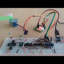
Step 7: Conclusions

It showed possible to make a working PIR controlled 433MHz switch without a micro controller.
However, it turned out to be somewhat more complicated than the one in the picture above, which uses an AtTiny85 micro processor, and has been running for years on the same batteries.


