Introduction: Personal Assistant for TB Diagnostic


Tuberculosis is a worldwide endemic disease with a high mortality rate, approximately 5 million people die each year. Despite being a disease completely curable, WHO data reveal that it is still being the third cause of mortality in the world. In the last decades, modern diagnostic methods have been developed, which diagnose the disease with a high sensitivity rate and in a few hours. However, developing countries cannot implement these new methods due to economic reasons, missing specialists and hard implementation in remote areas. For this reason, we are focusing on developing a set of embedded devices that modify and strengthen common laboratory instrumentation coupling mechanisms, circuits, microprocessors, SoCs and software with the finality of the automation of TB diagnostic.
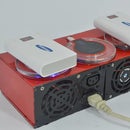
This is one of the embedded devices we´ve developed to help our main project of building an automatic digital microscope to detect disseases.
You can find full documentation and support by following us here!
https://hackaday.io/project/10188-automatic-digit...
This devices purpouse is to show the reports shown by the Automatic Digital Microscope implemented, as well as to store important data about clients. It also serves as partial controll of a biosecurity box and full control of the movement of the microscope.
Step 1: Getting All the Components
For this we will need:
- Raspberry pi3 (not tested on other rpis)
- 10 inch Capacitive Touchscreen
- Hdmi cable to trim down
- Usb Cables
- Powerbank (more than 20000 mAh for beter independence)
Step 2: Building the Case - Pt1

We wont go much into the build of it. The development was simple. The tablet came with the screen and touch attached together as well as to protective layers of acrylic. The controller board sat on top of all layers by screws and holders.
Step 3: Building the Case - Pt2
To atach the raspberry and the powerbank, we removed the second acrylic layer. Then we drilled new holes for the first acrylic layer to hold the lcd controller board. We did this by replacing screws by longer ones. This is to sit the raspberry below the controller since the ports of the lcd controller are facing down.
Step 4: Building the Case - Pt3
We also drilled the first acrylict to hold in place the raspberry pi.
Step 5: Building the Case - Pt4
Next we made all the wiring. For this we trimed down some usb cables as well as cutting the protectors on the edges replacing by electricall tape. As you can see, the lcd controlle board its absurdly long. They coulded done a better job developing it. This makes the build a lot more bulky.
Step 6: Building the Case - Pt5
Next, we found a nice spot for the power bank. We used the extra space for fitting a BIG powerbank. We added a painted wood with some nails and some putty to hold it in place.
Step 7: The Code! - Configuring Everything
In order to configure the Raspberry. check the video.
The code can be found on Github, here's the repo that you will need with all the files.
https://github.com/lozuwa/AI-Assistant


