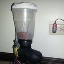
Introduction: Polargraph Implementation
I love this machine made and shared by Sandy Noble, I am just Sharing some personal learning tips to build a polargraph, I hope that helps someone else.
Step 1: Hardware
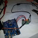
I am using Arduino Uno with Dual Stepper Motor Driver Shield (Bipolar) and bipolar stepper motor "mercury motor SM-42BYG011-25, printed some pulleys and gondola from http://www.thingiverse.com/
Step 2: Stepper Wiring
Step 3: Software
Downloaded from http://www.polargraph.co.uk/
Here are some tricks that I learn after a while.
1- before loading software to arduino (polargraph_server_a1.ino) change constant in
“byte const PEN_HEIGHT_SERVO_PIN = 10;” in polargraph_server_a1 tab. Why? Because default pin 9 matches stepper shield pin "Y MS2 SETTING" figure below related to velocity which in our case is set by jumpers. Obviously signal pin of the servo now need to be connected to pin10.
2- For this specific stepper motor shield please change this in configuration tab:
#ifdef SERIAL_STEPPER_DRIVERS
#define MOTOR_A_ENABLE_PIN16 //// my note: pin A2 in dual stepper shield "ENX"
#define MOTOR_A_STEP_PIN 2
#define MOTOR_A_DIR_PIN 3
#define MOTOR_B_ENABLE_PIN 14 /// my note Pin A0 in dual stepper shield "ENY"
#define MOTOR_B_STEP_PIN 6
#define MOTOR_B_DIR_PIN 7
3- Important PolargraphSD settings that you need to change on the setup tab or in default.properties.txt file:
Machine width in mm – use the value you measured using below instructions.
Machine height in mm – use the value you measured using below instructions.
mm per rev – set it to 95 (why? This is the length of string dealt out by one revolution of the motor)
Steps per rev – set it to 200 if you have a PolargraphSD v2 bought after July 2014, otherwise it should be 400 (why? This is the number of whole steps that the motor is capable of making)
Step multiplier – set it to 8 (why? This is the default microstepping value for the polarshield – this sets the internal resolution that the machine uses while moving)
When you press save properties in the top left corner, it saves your changes to it’s own internal properties file, so they will be there when you close and restart.
Note: to change values in Polargraph controller need to left click and hold during up-down movement motion of the mouse.
Also some parameters can be change in polargraphcontroller.exe but remember to change parameter need to hold left click and move mouse up and down. Don’t forget to “upload machine spec” {setup} for update all parameters in the arduino.
Step 4: Opening Polargraphcontroller.exe
1- Need to check arduino is communicating with the laptop “polar graph ready! (uno)” text need to be on green , not red. Also Queue need to be in green if red need to click over it, in case of the polargraph ready is not working need to configure port in setup tab / serial port
2- Click in “set home” {input tab} (motors will barely move)
3- Click on “set pen positon” {input tab} and click where the gondola is (again motors will barely move)
Step 5: Sketch
There are two types of drawing methods, one as sketch and other as shades
1- First how to draw as sketch:
In trace tab play with “simplify” and “posterise” to sharp
image then click on “capture” and “draw capture” will start to draw slowly, if you change to input tab will go faster, this type of drawing servo will be required.
Step 6: Drawing in Shade Mode
need to do it differently :
a. Need to home and set position
b. Instead of going into trace tab, need to stay in input tab and adjust image with
i. grid size (input)
ii. sample area (input)
c. Select Area (input) of the drawing you want to make
d. Set frame to Area
e. Need to send speed (setup)
f. Pentip size example :0.5 (setup)
g. Send pen tip size (setup)
h. Send speed (setup)
i. Remider pixels(input)
j. Generate Commands
Step 7: Append (Machine Measurements)
·
- Draw the top edge of your notional machine – this is a straight line directly in between your motor axes.
- Draw the sides of your notional machine. These are vertical lines that form a tangent on the inside radius of your sprockets. Just look at the pic
· Draw a parallel line marking where the top edge of your sheet of paper will go. This is 120mm from the top edge on my machine. If you have a wider machine (wider than about 800mm) then you might need to move this down proportionally.
· Mark a point in the centre of the second line. This is your home point and is the “magic” point that you’ll use to calibrate your machine before each drawing. In reality it doesn’t matter where it is on the machine, as long as you can measure it’s position accurately. I prefer to have it off the page though, so that it doesn’t get covered when I stick the sheet of paper up, and so that dropping the pen by accident doesn’t ruin my fresh sheet of paper.
Now, wield your tape measure and note down:
· The width of your machine – distance between the two edges. Remember the edges are the lines that run from the inside perimeter of your sprockets, NOT the physical edges of your board.
· The height of your machine – distance from the top edge to the floor.
· The home point position – distance from the top edge to the home point. This’ll probably be 120mm.


