Introduction: Proximity Drawer
Proximity Drawer is a hands-free Etch A Sketch-like drawer, using nothing but the distance between your hands and the two sensors to move the arm left, right, up, and down!
This was created for my #BCPhysComp "Make Art" project, where I didn't want to just make a piece of art, I wanted to make something that could create art.
Supplies
- Access to a 3D printer to print the following (see attachments):
- 1x frame.stl (optional)
- 1x arm_a.stl
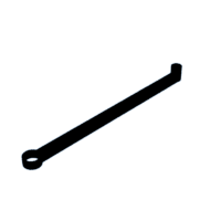
- 1x arm_b.stl
- 1x Arduino Nano RP2040 Connect running CircuitPython
- 2x 28BYJ-48 stepper motors with drivers
- 1x 5V power supply (separate from the Arduino)
- 2x VL53L1X TOF distance sensors
- 1x STEMMA QT to jumper cable
- 1x STEMMA QT to STEMMA QT cable for daisy chaining
- 1x counterweight. I used a rectangular magnet
- Breadboard and jumper wires to connect all the components
- Tape
- Paper
- 1x Sharpie
- 2 screws (or zipties)
For the optional wheel attachment to reduce friction on the second stepper motor, I used:
- 3D printed:
- 2x wheel_housing.stl
- 1x wheel_axle.stl
- The bearing from an Ender 3 extruder (13 mm diameter)
Step 1: Place the Arduino Onto the Breadboard
I like to place it with the usb port sticking out the end, so that the first pin is on number 1 of the breadboard.
Step 2: Connect the Motor and Jumper Wires to the Stepper Motor Drivers
Step 3: Connect the Stepper Motor Drivers to the Breadboard
Connect IN1-IN4 of stepper motor A to pins D9-D12 (numbers 4-1on the left of the Arduino) on the breadboard, and IN1-IN4 of stepper motor B to pins D5-D8 (numbers 8-5). Make sure the wires maintain the same order (IN1 to D9, IN2 to D10, etc). Connect the positive and negative terminals of the driver to the power rails on the breadboard.
Step 4: Connect the Distance Sensors to the Breadboard
Following the breadboard numbering, red should go to #2, blue to #8, yellow to #9, black to #14, to the right of the Arduino. Use the other STEMMA QT cable to daisy chain the distance sensors together.
To be able to read from both distance sensors, we also need to make use of the "XSHUT" pin. Connect the left distance sensor to D2 (#11 on the left) and the right sensor to D3 (#10 on the left). To connect it to the distance sensors, I bent the pins to a 90° angle and taped it to the bottom of the distance sensor, but you can also solder them in.
Step 5: (optional) Place the Breadboard, Stepper Motor A, Both Drivers, and the Counterweight Into the Frame
Step 6: (optional) Attach the Wheel to Arm A
Slide the two housings down the shaft, place the wheel on the axle, and snap it into place. This lifts stepper motor B from the paper, reducing friction and making it easier for stepper A to move.
Step 7: Attach the Arms to the Stepper Motor
- Place arm A onto stepper motor A.
- Attach Stepper motor B to the end of arm A, with screws or zipties.
- Place arm B onto stepper motor B
Step 8: Connect the Power Supply to the Breadboard Power Rails
Use a 5V power supply separate from the Arduino's power, so that movement in the steppers don't damage the Arduino.
Step 9: Reset the Position of Arms a and B
Place them so that arm A and arm B overlap, with the end of arm B sitting just past stepper A.
Step 10: Tape a Sheet of Paper Next to Stepper A
Place it so that the end of arm b is just above the left middle edge of the paper.
Step 11: Upload the Code Onto the Arduino
Upload code.py from https://github.com/pantherman594/proximity-drawer. Install all needed libraries (adafruit_motor and adafruit_vl53l1x) as well. Feel free to make any configuration changes in the top if needed.
Step 12: Wait for the Steppers to Move the End of Arm B to the Center of the Paper
Once the Arduino is powered, the steppers will automatically move until the end is right over the center of the page.
Step 13: Insert a Sharpie Into the End of Arm B, and Start Drawing!
Move your hand up and down above the left distance sensor to make the arm move left and right. The right sensor controls down and up.


![Tim's Mechanical Spider Leg [LU9685-20CU]](https://content.instructables.com/FFB/5R4I/LVKZ6G6R/FFB5R4ILVKZ6G6R.png?auto=webp&crop=1.2%3A1&frame=1&width=306)


