Introduction: Proxxon Micro Mill Semiautomatic-CNC


Hello! I’m a junior high student and this is my arduino project. This is an instruction about modifying proxxon mf-70 from full manual into semi-automatic. If you’re interested, please watch the video!
Video:
Step 1: Control Board-1


Material
- Aluminum (100x80x1mm)
- Wood board (120x200x12mm)
- Push switch
Tools
- Chisel (12, 30mm)
- Handsaw
- Jigsaw
- Drill
Method
Aluminum board
- Draw mark for inserting the push switches
- Drill hole that fits the push switches
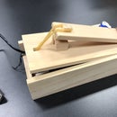
Wood board
- Use hand saw to cut the wood board into the size of
- Draw lines for inserting the aluminum board and LCD screen
- Use jig saw to saw out the lines
- Use 30mm chisel to make the side smoother
- Use 12mm chisel to cut out notch that can fit the LCD screen (like the picture above)
- Use 12mm chisel to cut out a slope at the edge of the LCD screen area (like the third picture above)
Step 2: Control Board-2


Material
- Led(Red and Green)
- LCD board https://www.amazon.com/SunFounder-Serial-Module-D...
- Screw m3
- Keypad (4x4) https://www.amazon.com/Matrix-Membrane-Switch-Key...
Tools
- The same
- Screwdriver
Method
Aluminum board
- Drill two more holes to place in the LEDs
- Insert it by placing it inside if it fits and not loosely or glue it on the wood
LCD screen
- Place the LCD board in the wood board
- Screw (like the picture above)
Key pad
- Drill holes in a line on the area that the wire has to go through
- Use 12mm chisel to make it square
- Make the wire go through the back of the wood board
- Wrap off the white layer of the key pad
- Stick it on the wood board
Step 3: Control Board-3


Material
- Arduino Nano
- Jump wires
- Breadboard
- Computer (downloaded Arduino)
Method
- picture above
Circuit
- Picture above
- LCD i2c (SDA-A4)black
- LCD i2c (SCL-A5)blue
- LCD i2c (VCC-5v+)red
- LCD i2c (GND-GND)black
- Push switch1 (the right one above the green LED-D13)green
- Push switch2 (the one at the left of this one↑-D11)Red
- Red LED (connect with the push switch2)
- Green LED (connect with the 5v+)
- Keypad (connect from D10 to D3)
Program
Step 4: Proxxon Micro Mill — Material


Material (for each axis)
- Thrust bearing x1 https://goods.ruten.com.tw/item/show?217422420585...
- Bearing adapter x1 (Pre-processing)
- Diameter 2mm axle x1
- Axle adapter 4.5-5mm x1
- Stepper motor x1 https://goods.ruten.com.tw/item/show?214051710720...
- Stepper motor adapter x1 (Pre-processing)
- m3 screw x3
- Copper pillar x3
- M3 Spacer x3
Tool
- Hex key (
- Vernier scale
Step 5: Pre-processing


Method
Stepper motor adapter (for x and y axis)
- Combine two cut 3mm acrylic board (design page dxf(1))
Disassemble the handle (x and y axis will be mostly the same)
- Unscrew the screw
- Remove the dial scale (there’s a small pin will pop out)
- Use a 1.9mm pin and a hammer to knock the pin for connecting the handle out
- Remove the black plate (pic 7)
- Drill three holes on it for connecting stepper motor (only for z axis)
Cutting the stepper motor axle (the shortened length will be different for x, y, z axis)
- Measure the length of the axle that has to be shortened (Mark it with marker)
- Use tape to protect the motor from the dust
- Use grinding wheel to cut the axle (wear gloves)
Cutting the copper pillar
- Measure the length of the copper pillar that has to be shortened (Mark it with marker)
- Use grinding wheel to cut the copper pillar (wear gloves)
Thrust bearing adapter (design page 3dm(1))
- Use CNC to mill aluminum to form the shape
- Mill a trench for fitting a 2mm pin (2mm mill head)
Step 6: X-axis


Method
- Screw the copper pillar on the stepper motor(do not screw it too hard)
- Screw the stepper motor adapter onto the three copper pillar with 3 m3 screws (the screws might have to be cut shorter to fit)
- Screw the axle adapter on the stepper motor axle (make sure it’s screwed on the flat surface of the shape axle)
- Insert the thread bearing onto the bearing adapter
- Screw the stepper motor adapter on the mill with two m3 screw
- Screw the axle adapter on the mill axle
Step 7: Y-axis


Method
- Screw the copper pillar on the stepper motor(do not screw it too hard)
- Screw the stepper motor adapter onto the three copper pillar with 3 m3 screws (the screws might have to be cut shorter to fit)
- Screw the axle adapter on the stepper motor axle (make sure it’s screwed on the flat surface of the shape axle)
- Insert the thread bearing onto the bearing adapter
- Screw the stepper motor adapter on the mill with two m3 screw
- Screw the axle adapter on the mill axle
Step 8: Z-axis


Method
- Screw the copper pillar on the stepper motor(do not screw it too hard)
- Screw the copper pillar on the black plate
- Insert the thread bearing onto the bearing adapter
- Screw the axle adapter on the stepper motor axle (make sure it’s screwed on the flat surface of the shape axle)
- Screw/unscrew the hex nut on the z-axis thread in order to adjust the position of the hex nut (Before the black plate was screwed on the mill
- Screw the black plate on the mill
- Soldering the stepper motor 4 line wire (If the order is incorrect)
Step 9: Stepper Motors Protection Cover


Method
- Use laser cutter to cut the acrylic in shape (Design page dxf(2))
- Use clamps to hold the acrylic (picture 5, 6, 7, 8, 9)
- Heat the acrylic with a heat blower (picture above)
- Drill two holes on one side on the acrylic (picture 11)
- Screw m3 screws on the acrylic with hex nut
- Attach the protection cover on the x, y axis (picture 14, 15, 16)
Step 10: Arduino + CNC Shield


CNC sheild https://goods.ruten.com.tw/item/show?2172447624178...
Connect Arduino uno with CNC shield
How to connect two Arduino
- connect Arduino nano tx to Arduino uno rx
- connect Arduino nano rx to Arduino uno tx
- Share the same GND
Step 11: Designs
File:https://drive.google.com/open?id=1sYZMpM7S5FVr36sa...
3dm files:
- axle adapter (for cnc)
- Whole layer (how to assemble layer1 and layer2)
dxf files:
- layer 1 (stepper motor adapter)
- layer 2 (stepper motor adapter)
- stepper motor protection cover
Step 12: How to Use the Control Board

How
- Push switch 2(above the red LED) Change mode:On-mode 2, Off-mode 1
- Mode 1
- A: x-axis
- B: y-axis
- C: z-axis
- *: move— +the variable
- #: move— -the variable
- 0: reset the coordinate to (0, 0, 0)
- 1: move 0.1mm
- 2: move 1mm
- 3: move 10mm
- Mode 2
- A: Feed rate
- B: Show coordinate
- Number key(has to push the push button 1(above the green LED) to key): key feed rate
- *: clear the feed rate
video:


