Introduction: Raspberry Pi Desk Notifier
I was thinking to make a Desk Notifier which will notify me about my new email, Facebook & Twitter notification and finally I made it. I used the coolest single board computer Raspberry Pi to bring the thing in reality. This Desk Notifier will notify you about your new Gmail, Facebook notification and will show you the total number of new emails, total number of likes of your Facebook page, total number of notifications of your Facebook account and number of your Twitter followers. You can easily modify it to show others information such as number of tweets, number of friend requests, number of messages etc. I used only two seven segment for each information to show and for that it can show maximum 99 notifications. You can easily extend it if you like.
Step 1: Required Tools
Components:
- Raspberry Pi (Dexter Industries) (Gearbest)
- SD Card with Raspbian operating system (Dexter Industries)
- Raspberry Pi WiFi Adapter (Dexter Industries)
- Raspberry Pi Power Supply (Dexter Industries)
- MAX7219CNG LED Driver IC (Sparkfun)
- Seven Segment Display (Common cathode- 8pcs)
- LED (5pcs)
- Resistor (10k- 1pc, 220ohm - 5pcs)
- PCB Board (8" x 4")
- PVC Board (12" x 10")
Tools:
- PCB Drill
- Soldering Iron
- Hot Glue Gun
- Scale
- Jumper Wire
- Wire Cutter
Step 2: Setup Raspberry Pi
To get started with Raspberry Pi you need an operating system. NOOBS (New Out Of the Box Software) is an easy operating system install manager for the Raspberry Pi. If you already bought a sd card with pre-installed operating system then just escape this step. If not follow NOOBS SETUP guide. You can follow the video from Raspberry Pi Foundation.
For more:
Instructables: All-in-One Raspberry Pi Getting Started Guide
Instructables:Getting started with Raspberry PI
Step 3: Setup & Test of Email Notification
You need to download and install few things in order for Python to be able to properly check your Gmail inbox and show the number of unread email in the seven segment display. Connect your Raspberry Pi to your PC using Putty and enter the following command to the terminal:
sudo apt-get install python-dev
sudo apt-get install python-pip
sudo pip install feedparser
sudo easy_install -U distribute
sudo apt-get install python-rpi.gpio
After executing all the command successfully try the following code snippet.
import RPi.GPIO as GPIO, feedparser, time

DEBUG = 1

USERNAME = "xxxxxxxx"     # just the part before the @ sign, add yours here
PASSWORD = "********"     # password of your email

NEWMAIL_OFFSET = 1        # my unread messages never goes to zero, yours might
MAIL_CHECK_FREQ = 60      # check mail every 60 seconds

while True:

        newmails = int(feedparser.parse("https://" + USERNAME + ":" + PASSWORD +"@mail.google.com/gmail/feed/atom")["feed"]["fullcount"])

        if DEBUG:
                print "You have", newmails, "new emails!"


        time.sleep(MAIL_CHECK_FREQ)
Copy the code into a file gmail-test.py or download the code directly from the link below. Transfer the file to home directory of Raspberry Pi using FileZilla and run the following command from the terminal:
sudo python gmail-test.py
If everything works well you will get following output.

Attachments
Step 4: Setup & Test of Facebook Notification & Like Count
We will access our Facebook account using Facebook Graph API. Most request of Graph API need an access token as a parameter. An access token is unique to the combination of a logged in user or page and the Facebook App that makes the request. A token is associated with a Facebook app to handle the permissions that the user has granted to the app.
To get Access Token follow the steps:
1. Go to https://developers.facebook.com/tools/explorer
2. Click the button on the right to Get Token Drop Down came down to it.
3. Choose to Page Access Token

4. Select necessary field from the left side and click Submit.

5. Copy Access Token & id. We will use it to our program.
OK, we got the Access Token.
Now, we need to install some python module to work with Facebook. Go to terminal window and type the following command:
sudo pip install urllib2
Wait for a while. OK, your urllib2 module is now installed. Copy the code snippet into facebook-test.py or download the attached file directly.
import urllib2
import json
import time

def get_page_data(page_id,access_token):
    api_endpoint = "https://graph.facebook.com/v2.4/"
    fb_graph_url = api_endpoint+page_id+"?fields=id,name,likes,unread_notif_count,link&access_token="+access_token
    try:
        api_request = urllib2.Request(fb_graph_url)
        api_response = urllib2.urlopen(api_request)

        try:
            return json.loads(api_response.read())
        except (ValueError, KeyError, TypeError):
            return "JSON error"

    except IOError, e:
        if hasattr(e, 'code'):
            return e.code
        elif hasattr(e, 'reason'):
            return e.reason

while 1:
    page_id = "1664109577184012" # username or id
    token = "CAACEdEose0cBAKBSd9olmJZA3rMZCUy4XZB8qDXwiM49G4OgfYbJQHYNWmyzcFnuTeunGyQZBZChcaEoC8uEjTZCNyWpPtvIWEOkEY7H5AZBFEmZBAFeXEYjzCCOob1ZAK6qwIMskMBQdLjcWBJpM5ZCIeUytLAWTgJwkeXZCwZChzeX5hZCk3kEZC86w25KfmItZBHepMJIZA67VYBYCgZDZD"  # Access Token
    page_data = get_page_data(page_id,token)

    print "Page Name:"+ page_data['name']
    print "Likes:"+ str(page_data['likes'])
    print "Unread notifications:"+ str(page_data['unread_notif_count'])

    time.sleep(0.5)
Transfer the file to Raspberry pi and run it using the command:
sudo python facebook-test.py
If everything works well you will get output like following.

Attachments
Step 5: Setup & Test of Twitter
To access your Twitter account you need Access Key. Click here to learn how to get Twitter Access Key. Got it? Now, we need to download tweepy, an excellent python module to access Twitter API. To download and install just type the command:
sudo pip install tweepy
We are ready with Access Key and required module. It is the time to make fun with it. Copy the code snippet and save it to twitter-test.py.
import oauth, tweepy, sys, locale, threading
from time import localtime, strftime, sleep

def init():
    global api
    consumer_key = "xxxxxxxxxxxxxxxxxxxxxxx" # your access key
    consumer_secret = "xxxxxxxxxxxxxxxxxxxxxxxxxxxxxxx"
    access_key = "xxxxxxxxxxxxxxxxxxxxxxxxxxxxxxxxx"
    access_secret = "xxxxxxxxxxxxxxxxxxxxxxxxxxxxxxxxxx"
    auth = tweepy.OAuthHandler(consumer_key, consumer_secret)
    auth.set_access_token(access_key, access_secret)
    api = tweepy.API(auth)

    user = api.get_user(3318190836)
    print "User: " + user.screen_name
    print "Followers: " + str(user.followers_count)
    print "Friends: " + str(user.friends_count)
    print "Favorites: " + str(user.favourites_count)
    #print api.direct_messages()
init()
If it works well you will get following output.

Attachments
Step 6: Interfacing of Raspberry Pi & MAX7219 LED Driver
The MAX7219 lets us control lots and lots of LEDs using just a few Raspberry Pi pin-outs. No hassles with multiplexing, latching, refreshing or using up all your outputs – it handles everything for us. We just send commands to the MAX7219 and we can control up to 64 LEDs (a 8x8 LED Matrix) or eight seven (8 including the decimal point) segment displays, you can even chain multiple MAX7219s together to drive loads more. All this via just a few pins.
Both the Raspberry Pi and the MAX7219 support SPI (Serial Peripheral Interface), a good idea then to the get the RPi to talk to a MAX7219 via its very own SPI interface. By default SPI protocol is turned off but you can enable it very easily and can send and receive data.
Before going further, lets connect Raspberry Pi to MAX7219 IC. Here is the pin out:
| MAX7219 Pin | Name | Remarks | RPi Pin | RPi Function |
|---|---|---|---|---|
| 19 | VCC | +5 Volt Supply | 2 | 5 V |
| 4, 9 | GND | Ground | 6 | Ground |
| 1 | DIN | Data In | 19 | GPIO 10 (MOSI) |
| 12 | CS | Chip Select | 24 | GPIO 8 (SPI CE0) |
| 13 | CLK | Clock | 23 | GPIO 11 (SPI CLK) |
We have completed connection. Now, lets enable SPI interface of Raspberry Pi. To do this,
1. Open terminal and type:
sudo raspi-config
A configuration window will appear like below.
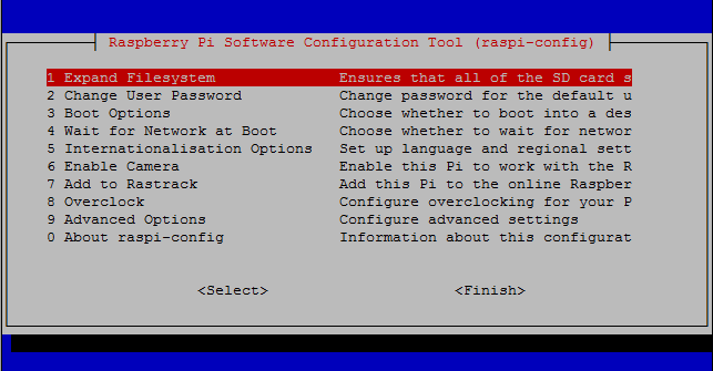
2. Press down arrow key and select Advanced Options & click Enter.

3. Select SPI and click Enter
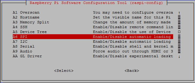
4. It will ask for confirmation, just press Enter to yes.
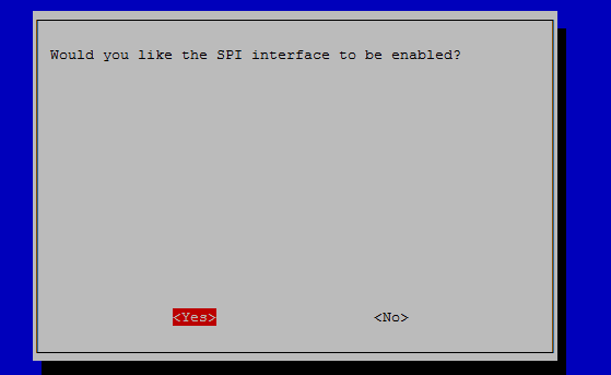
5. After confirming a new window will appear asking you like to load kernel default or not. Select yes.
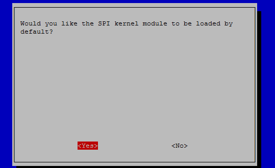
5. You may ask to restart your Pi. Restart it. Now your SPI interface is enable.
Cascading, power supply & level shifting
The MAX7219 chip supports cascading devices by connecting the DIN of one chip to the DOUT of another chip. You can control lots of seven segment display or led matrix by cascading several MAX7219 IC.
Raspberry PI can only supply a limited amount of power from the 5V and 3.3V rail, so it is recommended that any LED matrices or seven segment are powered separately by a 5V supply, and grounded with the Raspberry PI. It is possible to power one or two LED matrices directly from a Raspberry PI, but any more is likely to cause intermittent faults & crashes.
Raspberry Pi GPIO ports used 3.3V for SPI, and MAX7219 IC operate on 5V so a simple level shifter should be employed on the DIN, CS and CLK inputs to boost the levels to 5V. It is possible to drive the IC directly by the 3.3V GPIO pins and in case of mine it works well. As I am driving the IC from 3.3V GPIO pins directly for that I used 3.3V supply for the VCC pin of the IC. I experimented with 5V but I got better stability from 3.3V supply. A 3.7V Li-ion battery works very well. You can use Li-ion battery directly to bias MAX7219 IC.
Step 7: Make the Circuit Diagram
The circuit diagram is designed by Eagle schematic editor. Source file is attached below. If you notice, a 10k resistor is connected between ISET and VCC pin of MAX7219CNG LED driver is. This resistor act as current limiter. I used 10k for 40mA segment current. You can find details about the value of this resistor to manufacturer datasheet.
Eight common cathode seven segment LED display is used for displaying four information. Two 7 segment for each information and for that it can show maximum value of 99. You can use more display for displaying greater value. The reason for using common cathode display is that, MAX7219 driver IC can drive common cathode display only.
I used 8 LED into four pin, each has two parallel LED which will blink when new notification or email arrived. Pin header SV1 is used to connect with Raspberry Pi and power source.
Step 8: Design of PCB
PCB layout was designed using Eagle software. Four display group was created containing two seven segment in each group as I want to show four information. I created a provision for connecting LEDs above the displays. I did not implement it now but you can use it to blink when a new notification will come. In the last stage you will see i used the logo of Gmail, Facebook & Twitter at the bottom of the display to specify which information it is showing. You can use led at the bottom of the logo to make it bright. Option is there, you can use it in your own way.
Step 9: Make the PCB (Toner Transfer Method)
I made the PCB for my project using toner transfer method. Toner transfer method is an excellent method for DIY PCB making. There are many excellent methods are available in the internet about DIY PCB making, so I don't like to explain it here. If you are interested about toner transfer method then you can follow:
1. PCB Etching Using Toner Transfer Method
Step 10: Drill the PCB
After etching the PCB you have to drill the PCB board. I use home made mini drill to drill the PCB. For details just follow the instructables: DIY Pcb Hand Drilling Machine.
Step 11: Solder All the Components
If you had made and drilled your PCB now it is the right time to put all the components to the PCB board and solder them. Some soldering technique is required to do the job nicely. Are you new in soldering? Have no previous experience in soldering? Don't panic! Soldering is an easy task!! Just follow the links:
1. Instructables: How to solder - the secrets of good soldering
Step 12: Make the Box (Cut PVC)
A box is required to fit all the component and Raspberry Pi. I made the box using 4mm thick PVC board. Just cut the board as your requirement depends on the size of your box. I made the box of dimension 20mm x 9mm x 5.5mm. For that I made:
2 pcs 20mm x 9mm
2pcs 20mm x 5.5mm
2pcs 9mm x 5.5mm
If you have access to leaser cutter then you can make more nice and elegant box using plywood.
Step 13: Make the Box (Use Hot Glue)
As I have no enough tools to make a nice box, I used hot glue to make a DIY box and I discovered that it is strong enough to make a box for such project. I just use the glue only inner side of the box and enough for it. I uploaded some image of my PVC box. Make your box without the upper part. For upper part follow the next step.
Step 14: Make the Box (Upper Part)
Yes, it is the time to make the upper part of our box. Make four holes according to the seven segment display to fix the circuit previously made. Consider the distance between the holes when making the hole. Make a measurement using roller. I used pencil to make the draft drawing to the back side of the board. This will help you to make the hole perfect.
Step 15: Attach the Circuit to the Upper Part
If you cut your board perfectly it will fit with the circuit board made earlier. Attach the circuit board to the upper part of the box. If it fit perfectly then congratulation! Now you can test your circuit either it is working or not. I am sure your circuit will work perfectly. I attached some image of working circuit. It is not our complete project. Just for demo testing.
Step 16: Let's Test
We are almost ready to test our circuit and configuration. Before testing we need some more download. To communicate with MAX7219 from Raspberry Pi we will use max7219 Python module. To download and install the module type the following commands:
sudo pip install spidev
git clone https://github.com/rm-hull/max7219.git
sudo python max7219/setup.py install
We are completely ready to go. Type the following command into terminal
python
You will get like bellow

Now, type the following commands
import max7219.led as led
device = led.sevensegment()
device.write_number(deviceId=0, value=3.14159)

Is the value of pi is displayed into your display board? Congratulation!!! You made it.
Step 17: Complete Your Setup
Now fix the upper part along with the circuit to the box included with Raspberry Pi. Run the python program attached with the next step. The notifier will notify you about your new unread email, your Facebook notifications, total like of your Facebook page, Total follower of your Twitter account. You can easily modify the program to display others information such as friend requests, total unread Facebook message etc. Even you can use it to display the time & date as use it as a desk clock.
Are you ready to run the complete program? Follow the net step.
Step 18: Run the Complete Program
We completed all of the steps to make the physical thing. Now it is the high time to make the thing live using complete Python program. Clearly follow the program and replace "xxxxxxxxxxxxxxx" marks with your information.
#!/usr/bin/env python

import RPi.GPIO as GPIO, feedparser, time

import urllib2
import json
import time

import oauth, tweepy, sys, locale, threading
from time import localtime, strftime, sleep

import max7219.led as led
device = led.sevensegment()

###### Gmail
DEBUG = 1

USERNAME = "xxxxxxxxxxxxxx"     # just the part before the @ sign, add yours here
PASSWORD = "**********"

NEWMAIL_OFFSET = 1        # my unread messages never goes to zero, yours might
MAIL_CHECK_FREQ = 60      # check mail every 60 seconds

##################### gmail

GPIO.setmode(GPIO.BCM)

GREEN_LED = 1
RED_LED = 2
GPIO.setup(GREEN_LED, GPIO.OUT)
GPIO.setup(RED_LED, GPIO.OUT)

def gmail():
        global mail

        newmails = int(feedparser.parse("https://" + USERNAME + ":" + PASSWORD +"@mail.google.com/gmail/feed/atom")["feed"]["fullcount"])

        if DEBUG:
                print "You have", newmails, "new emails!"
                mail = newmails
        if newmails > NEWMAIL_OFFSET:
                GPIO.output(GREEN_LED, True)
                GPIO.output(RED_LED, False)
        else:
                GPIO.output(GREEN_LED, False)
                GPIO.output(RED_LED, True)

        #time.sleep(MAIL_CHECK_FREQ)

def get_page_data(page_id,access_token):
    api_endpoint = "https://graph.facebook.com/v2.4/"
    fb_graph_url = api_endpoint+page_id+"?fields=id,name,likes,unread_notif_count,unread_message_count,link&access_token="+access_token
    try:
        api_request = urllib2.Request(fb_graph_url)
        api_response = urllib2.urlopen(api_request)

        try:
            return json.loads(api_response.read())
        except (ValueError, KeyError, TypeError):
            return "JSON error"

    except IOError, e:
        if hasattr(e, 'code'):
            return e.code
        elif hasattr(e, 'reason'):
            return e.reason

def facebook():
    global like_count
    global notification_count
    page_id = "xxxxxxxxxxxxxxxx"
    # username or id <a href="https://developers.facebook.com/tools/explorer"> https://developers.facebook.com/tools/explorer</a>

    token = "xxxxxxxxxxxxxxxxxxxxxxxxxxxxxxxxxxxxx"  # Access Token
    page_data = get_page_data(page_id,token)

    print "Page Name:"+ page_data['name']
    print "Likes:"+ str(page_data['likes'])
    like_count = page_data['likes']
    print "Link:"+ page_data['link']
    print "Unread notifications:"+ str(page_data['unread_notif_count'])
    notification_count = page_data['unread_notif_count']
    print "Unread message:"+ str(page_data['unread_message_count'])

    #time.sleep(0.5)

def twitter():
    global follower
    global api    #https://apps.twitter.com
    consumer_key = "xxxxxxxxxxxxxxxxxxxxxx"  # use your access key
    consumer_secret = "xxxxxxxxxxxxxxxxxxxxxxxxx"
    access_key = "xxxxxxxxxxxxxxxxxxxxxxxxxxxx"
    access_secret = "xxxxxxxxxxxxxxxxxxxxxxxxx"
    auth = tweepy.OAuthHandler(consumer_key, consumer_secret)
    auth.set_access_token(access_key, access_secret)
    api = tweepy.API(auth)

    user = api.get_user(xxxxxxxxxx)  # your user id
    print user.screen_name
    print user.followers_count
    follower = user.followers_count
    print user.friends_count
    print user.favourites_count

def reverse(n):
    if(n<10):
	    return n*10
    else:
        return int(str(n)[::-1])

def display():  # form a number from all information
    all_value = (reverse(follower) * 1000000) + (reverse(like_count)*10000) + (reverse(notification_count)*100) + reverse(mail)
    print all_value
    device.write_number(deviceId=0, value=all_value)

while True:
        gmail()
        facebook()
        twitter()
        display()
        time.sleep(0.6)
You can download the source file attached below. Run the program using the following command:
sudo python iot-dashboard.py
If it works fine then CONGRATULATION!!!!
If you want to load the program automatically after reboot of raspberry pi then follow the instructions:
1. Make your file executable using the command:
sudo chmod +x iot-dashboard.py
You can test it by running the program directly by typing:
./iot-dashboard.py
Even though you didn't call upon Python the program should still run the same as if you'd typed python iot-dashboard.py. The program can only be run by calling it with it's full location /home/pi/iot-dashboard.py or from the current directory by using ./ as the location.
2. Make the program auto running:
In order to have a command or program run when the Pi boots, you can add commands to the rc.local file. This is especially useful if you want to be able to plug your Pi in to power headless, and have it run a program without configuration or a manual start.
2.1 On your Pi, edit the file /etc/rc.local using the editor of your choice. You must edit with root, for example:
sudo nano /etc/rc.local
2.2 Add commands below the comment, but leave the line exit 0 at the end, then save the file and exit.
python /home/pi/iot-dashboard.py &
Now reboot your Pi and enjoy Your Desk Notifier. You Made it!!!
Attachments

Second Prize in the
Raspberry Pi Contest 2016

Participated in the
Hand Tools Only Contest 2016

Participated in the
Full Spectrum Laser Contest 2016

Participated in the
Hack Your Day Contest


