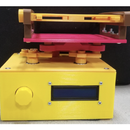
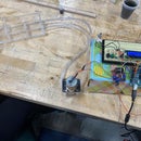
Introduction: Rayleigh-Plateau Instability Demo
The Rayleigh-Plateau instability manifests every time you turn on a faucet; it’s how a stream of fluid starts as a smooth cylinder and breaks apart into discrete droplets. When set up carefully, you can get incredible visualizations of this phenomenon! With the help of these instructions, you can build your own simple demonstration apparatus to visualize and quantify Rayleigh-Plateau instability, and to show how the length at which the stream breaks apart depends on nozzle radius.
To learn more about the Rayleigh-Plateau instability and the demo design, check out our blog posts at https://blogs.brown.edu/engn1860rd/group-2/
This device can be used to teach high school students about fluid dynamics, the study of the flow of liquids and gases. For more information, see step 10, where we've included a lab manual for your use.
The second image for this step shows a basic schematic of our finished demo. This design can be easily modified to fit your purpose and material constraints, but is a useful way to visualize the basic components. Most materials listed here can be adjusted or substituted to fit your purposes and resources.
Basic Components:
- Upper and lower platforms with holes in their centers (to allow fluid to pass through)
- Supports between the upper and lower platforms that don’t obstruct the phenomenon
- Flat backboard (to go behind the phenomenon)
- Water pump1 tub to go under the lower platform1 tub to go on top of the upper platform, with a hole in the center for the nozzle
- Tubing long enough to go from the lower tub to the upper tub
- Overflow reservoir fixed into the hole in the upper tub (to keep measurements accurate)
- At least 2 nozzles with different hole sizes that can be attached to the fluid reservoir with a watertight seal
- A scale near the fluid stream to quantify fluid flow
- WaterPhone with strobe capacity [free “strobelight” app on the app store]
Recommended Materials:
- 3/4” inner diameter PVC pipe, 2 20” pieces [24" piece from Home Depot]
- ¼” plywood sheet, 2 12”x18” pieces [2'x4' sheet from Home Depot]
- 1/2” thick wood board, 20”x10” piece [2'x4' piece from Home Depot]
- L-brackets, 4 [1.5" 20 pack from Home Depot]
- 10-32 1” bolts, 10-32 nuts [Phillips machine screws from McMaster-Carr & hex nut from McMaster-Carr]
- 6 quart plastic tubs, 2 [Sterilite 2-pack from Amazon]
- Small water pump [Fish tank pump, 300L/H, 4W from Amazon]
- ~½” tubing [3/8" OD, 5/16" ID, 10' long piece from Amazon]
- 2 beverage bottles (same kind)
- Deionized water, 4 liters
Alternate Materials:
- In place of plywood: ¼” acrylic sheet, 2 12”x18” pieces (more waterproof but more difficult to cut)
- In place of 1” thick wood board: anything smooth & flat that can be drilled into, including more plywood. The thicker wood was chosen for added stability. Lighter colors are helpful for visualizations.
- To test the effect of fluid velocity: use another plastic tub and beverage bottle, and cut the beverage bottle to a different height. The change in amount of fluid “above” the nozzle will change the speed of the fluid exiting the nozzle.
Step 1: Cut the Plywood to Form the Upper and Lower Platforms
If you have access to a laser cutter, you can use the Adobe Illustrator or .dxf file attached below.
If not, you can cut the plywood to size using saws and add the screw holes with a drill.
Step 2: Cut the PVC and Backboard to Size
Cut the PVC to 20” lengths. Cut the backboard to 20” tall and at least 10” wide.
Step 3: Add Screw Holes
Add screw holes in the PVC 0.5” from either end using a #21 drill bit (or wherever the holes on your L-bracket would be).
Add screw holes to the upper and lower platforms according to the drawing below (or wherever the holes on your L-bracket would be) using a #21 drill bit. Similarly, add a ½” hole for the tubing.
Step 4: Make a Ruler
If you have access to a laser cutter, you can use the Adobe Illustrator file or .dxf attached below and have it slot into the upper and lower platforms. Otherwise, you can take an existing meter stick and cut it to size (20” long) and use L-brackets to hold it in place.
You want the ruler to be in line with where the fluid will fall to ensure more accurate measurements.
Attachments
Step 5: Assemble the Frame
Step 6: Drill Holes in the Plastic Tubs
In both tubs, drill a ½” hole near the brim.
In one tub, drill a hole in center of the bottom large enough to nest the beverage bottle in.
Step 7: Prepare Fluid Reservoir & Nozzles
The reservoir ensures constant fluid pressure. So long as it remains full, the hydrostatic pressure, and thus fluid velocity, should stay constant. The upper tub catches the overflow.
Cut off the bottom of a beverage bottle. Drill a hole into the lid with a #31 bit. In another beverage bottle lid of the same type, drill a hole with a ¼” bit. Glue the reservoir into the upper tub, making sure to keep it as level as possible.
Step 8: Combine All Systems
Place the upper tub on the upper platform and the lower tub under the lower platform. Attach the tubing to the pump and place the pump in the lower tub. Feed the tubing through the lower tub, through the PVC pipe, through the upper platform and tub, and into the reservoir.
Step 9: Phone Stand (optional)
If it helps with consistent data collection, build a simple phone stand such as the Laser Cut Phone Stand by Pitakire on Instructables [here].
Step 10: Use This Demo As a High School Physics Lab
You can use the attached lab manual to teach high school physics students about the Rayleigh-Plateau instability. Fluid dynamics is a subfield of physics that isn't usually introduced until college, but this lab manual makes the concept accessible and will hopefully engage and excite high school students about pursuing a career in a STEM field.
Attachments

Participated in the
Classroom Science Contest


