Introduction: Redbear BLE Nano V2 Custom Controls With PfodApp -- No Coding Required


Update: 15th Sept 2017 -- This instructable has been updated to use the latest version of RedBear BLE Nano, V2. The previous version of this instructable, which targeted RedBear BLE Nano V1.5 is available here.
Update 15th November – 2017 Some BLE boards / software stacks deliver the same cmd twice in quick succession. Update to pfodApp V3.322+ and pfodParser V3.17+ to solve this. pfodApp V3.322+ adds a cmd sequence number and pfodParser V3.17+ filters out duplicate cmds
None of these screens are hard coded into pfodApp (the Android app).
All the screens above are completely controlled by the code in your RedBear BLE Nano V2.
This tutorial covers custom controls for the RedBear BLE Nano V2 module. It is in two parts:-
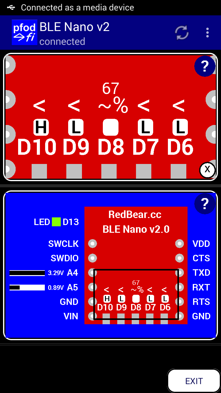
The first part presents a “starter” sketch, that when loaded into your RedBear BLE Nano V2, will display an interactive graphic on pfodApp that will let you read the Analog and Digital inputs. Change the digital pins to outputs/PWM and set the output/PWM values.
The second part uses the free pfodDesigner to create custom multi-levels menus, plots and data logging that can be displayed on pfodApp. The pfodDesigner generates all the Android code needed for the RedBear BLE Nano V2. The general purpose pfodApp handles the user display and interaction on your Android mobile. The user display is completely controlled by the Android code you load into your Nano. No Android programming is required.
Step 1: The RedBear BLE Nano V2 Starter Sketch
The animated GIF above shows the operation of the RedBear BLE Nano V1.5 Starter Sketch.
To run this sketch you need:-
- RedBearLab BLE Nano V2 Kit – BLE Nano module and programming module http://redbearlab.com/buy/ ~US $30
- USB extension cable (optional but useful) – https://www.sparkfun.com/products/13309 ~US $2
- pfodApp – Android app http://redbearlab.com/buy/ ~US 10
- Arduino IDE V1.8.4 – http://redbearlab.com/buy/
- and supporting libraries (see note below about updating the BLEPeripheral library from V0.4.0 to V0.5.0)
Step 2: Installation of the Starter Sketch

- Install Arduino IDE V1.8.4 from https://www.arduino.cc/en/Main/Software
Follow the Arduino install guide https://github.com/redbear/nRF5x/blob/master/nRF5...
Add https://redbear.github.io/arduino/package_redbear... the Arduino Additional Boards Manager URLs (under File->Preferences) and then use the Arduino Board Manager to install the RedBear nRF52832 boards V0.0.2 ( filter your search to RedBear)- Install the BLEPeripheral library. Open the Library Manager in the Arduino IDE and type BLEPeripheral in the search bar. Select BLEPeripheral by Sandeep Mistry V0.5.0 and install it.
Note: BLEPeripheral V0.5.0 is not released as of 14th September 2017, so install V0.4.0 and then overwrite the nRF51822.h and nRF51822.cpp files with the updated files in this zip file, nRF51822.zip. A copy of that V0.4.0 arduino-BLEPeripheral-master.zip file is here .
- Manually download and the pfodParser.zip and pfodDwgControls.zip libraries from here and then use Arduino IDE menu option Sketch → Import Library → Add Library to install them.
- Unzip this sketch RedbearBLENanoV2Starter.zip and its supporting classes to your Aduino Sketchbook location (shown in File → Preferences).
- Open the Arduino IDE, select the BLE Nano board, (my board was V1.5) and open the RedbearBLENanoV2Starter.ino sketch and compile and download to the BLE Nano V2 module. To program it you need to add the USB shield shown above (under the main board). While the USB shield is designed to plug directly into your USB port, I found that very inconvenient on my laptop so I add a USB extension cable. The BLE Nano V2 now contains all the code necessary to draw the interactive graphic and process the user's inputs.
- Install pfodApp on your Android Mobile. You will need a mobile with Android OS V4.4 or higher and one that supports Bluetooth Low Energy. Then create a BLE connection to your BLE Nano, as described in pfodAppForAndroidGettingStarted.pdf. Finally connect, and pfodApp will load the graphic shown above. Once the graphic is loaded, pfodApp caches it so next time the BLE Nano V2 only needs to send the updates.
The sketch you have loaded uses pfodApp drawing primitives to draw the board outline and buttons and to define the user touch zones and actions. The Custom Arduino Controls for Android tutorial covers how to code your own custom controls and the Arduino101 Starter, controlled by Android/pfodApp tutorial describes how the Zoom and Pan works.
The next section describes how to use the free WISIWYG pfodDesigner to create multi-level menus to control the outputs and read and plot and log the analog inputs and generate all the code required for your RedBear BLE Nano.
Step 3: Creating the Custom Android Menus for RedBear BLE Nano and Generating the Code

The free pfodDesignerV2 Android app lets you create custom menus and then generates all the code for your particular BLE module. pfodApp is then used to display your custom menu on your Android mobile and let you control your module.
No Android or Arduino coding is required.
The free pfodDesignerV2 is used to create the menu in a WISIWYG fashion and show you an accurate preview of how the menu will look on your mobile. The pfodDesignerV2 allows you to create menus and sub-menus with buttons and sliders optionally connected to I/O pins and generate the sketch code for you (see the pfodDesigner example tutorials) but the pfodDesignerV2 does not cover all the features pfodApp supports. See the pfodSpecification.pdf for a complete list including data logging and plotting, multi- and single- selections screens, sliders, text input, etc.
Create the Custom menu to turn the RedBear BLE Nano V2 LED on and off
The tutorial Design a Custom menu to turn the Arduino Led on and off has step by step instructions for creating this menu using pfodDesignerV2. If you don't like the colours of font sizes or the text, you can easily edit them in pfodDesignerV2 to whatever you want and see a WYSIWYG (What You See Is What You Get) display of the designed menu.
There is only one change to make for RedBear BLE Nano V2 and that is to set it as the Target for the code generator for the new menu before adding the Led control menu item.
Step 4: Choosing RedBear BLE Nano V2 As the Target for the Code Generation


First you need to choose RedBear BLE Nano as the Target for the code generation. When you start a new menu or edit an existing menu, the top button shows the Target board. The default is Serial.
Click on the Target button to open the Target selections.
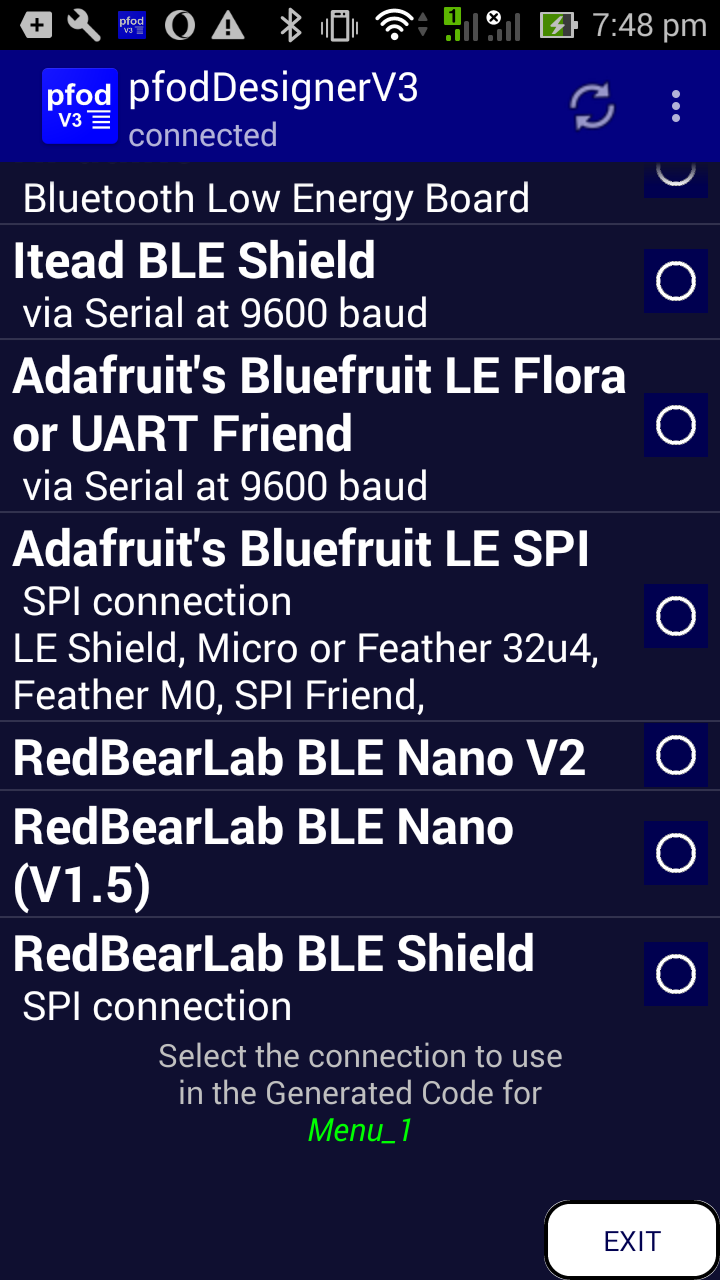
Choose Bluetooth Low Energy button and scroll down to find the RedBearLab BLE Nano V2 option and click on it.
Then use the mobile's back button to exit the Target selections screen and return to the Edit Menu screen.
Step 5: Swapping the On/Off Indicators -- Not Need for BLE Nano V2

The previous version, The RedBear BLE Nano V1.5 had another difference. It's LED is active LOW. That is when the output from D13 is LOW the led is ON.
On Nano V2, the LED is active HIGH so nothing to do here.
That completes the changes needed. You can now continue with the Design a Custom menu to turn the Arduino Led on and off tutorial to Generate the Code, transfer it to your computer and compile and download to your RedBear BLE Nano V2. A copy of the generate code sketch is here (BLENanoV2LedController.ino)
Then connect via pfodApp from your mobile to display the menu you have just designed and control the Led by either clicking anywhere in the button or sliding the slider.
Step 6: Enhanced BLE Nano Control Menu


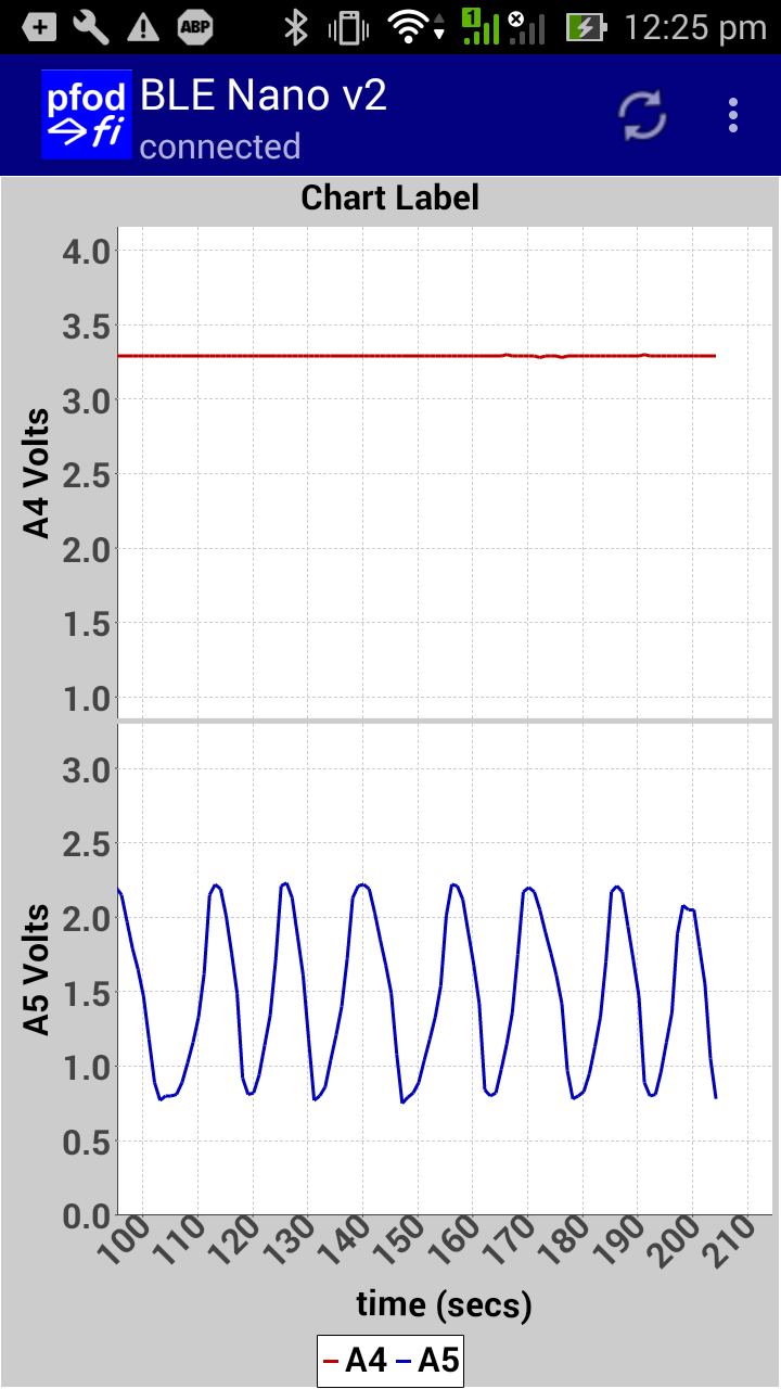
Using the Led Controller as a basis, you can add more menu items for reading or controlling the other Digital pins and for reading, plotting and logging the Analog inputs, A4 and A5. Check out the various pfodDesigner tutorials on using the various menu items. The How to Display Arduino Data on Android for Beginners tutorial covers creating plots.
The generated sketch is here (BLE_NanoV2Controller.ino)
As well as plotting the Analog values, the readings are also logged, in CSV format, to a file on your mobile for later use.
Sample Screens
The pfodDesignerV2 only supports a sub-set of the screens that pfodApp supports. For a complete list see the pfodSpecification.pdf. The SampleRedBearBLENanoV2Screens.ino sketch includes additional screens supported by pfodApp but not included in the pfodDesigner. Most of the screens have no formatting to keep the messages clear and simple. The color selector under Sliders is an exception. You can add your own colours and font styles, using the pfodDesignerV2 as a guide. Also see the pfodDemo Android app for other examples.
The SampleRedBearBLENanoV2Screens.ino sketch needs the pfodParser.zip and pfodDwgControls.zip libraries to be installed first.
Conclusion
This tutorial has shown how you can easily communicate with and control RedBearLab BLE Nano boards
No Android programming is required. pfodApp handles all of that.
No Arduino coding is required. The (free) pfodDesignerV2 generates complete sketches for this and a variety of other modules including ESP8266 and WiFi, Bluetooth and SMS shields.
Because there is no standard for a general purpose UART connection to a BLE device, pfodApp has pre-configured a number of the common BLE boards' connection parameters so you can use the same pfodApp for all of them.

Participated in the
Bluetooth Challenge


