Introduction: Arduino Interfacing With Ultrasonic Sensor and Contactless Temperature Sensor


Nowadays, Makers, Developers are preferring Arduino for rapid development of the prototyping of projects. Arduino is an open-source electronics platform based on easy-to-use hardware and software. Arduino has very good user community.
In this project we will see how to sense object’s temperature and distance. The object can be of any type like hot jar or real cold ice cube wall outside. So, with this system we can be save our-self. And more importantly this can be helpful for disabled person (blind people).
Step 1: Component


For this project we will need following components,
1.Arduino Nano
Arduino Nano in India- https://amzn.to/2Jy1gYJ
Arduino Nano in UK - https://amzn.to/2Jy1gYJ
Arduino Nano in USA - https://amzn.to/2Jy1gYJ
2.MLX90614 (IR Temperature sensor)
MLX90614 in India- https://amzn.to/2C4E5Br
MLX90614 in UK - https://amzn.to/2C4E5Br
MLX90614 in USA - https://amzn.to/2C4E5Br
3.HCSR04 (Ultrasonic sensor)
HC-SR04 in India- https://amzn.to/2N93a48
HC-SR04 in UK - https://amzn.to/2N93a48
HC-SR04 in USA - https://amzn.to/2JusLCu
4.16x2 LCD
16X2 LCD in India- https://amzn.to/34nsdGF
16X2 LCD in UK - https://amzn.to/34nsdGF
16X2 LCD in USA - https://amzn.to/34nsdGF
5.Breadboard
BreadBoard in India- https://amzn.to/2MW0Opb
BreadBoard in USA- https://amzn.to/2MW0Opb
BreadBoard in UK- https://amzn.to/2MW0Opb
6.Few Wires We can use any Arduino board instead of Arduino nano considering pin mapping.
Step 2: More About MLX90614:

MLX90614 is i2c based IR temperature sensor works on thermal radiation detection.
Internally, the MLX90614 is a pairing of two devices: an infrared thermopile detector and a signal-conditioning application processor. Per the Stefan-Boltzman law, any object that isn't below absolute zero (0°K) emits (non-human-eye-visible) light in the infrared spectrum that is directly proportional to its temperature. The special infrared thermopile inside the MLX90614 senses how much infrared energy is being emitted by materials in its field of view, and produces an electrical signal proportional to that.
That voltage produced by the thermopile is picked up by the application processor's 17-bit ADC, then conditioned before being passed over to a microcontroller.
Step 3: More About HCSR04 Module:


In ultrasonic module HCSR04, we have to give trigger pulse on trigger pin, so that it will generate ultrasound of frequency 40 kHz. After generating ultrasound i.e. 8 pulses of 40 kHz, it makes echo pin high. Echo pin remains high until it does not get the echo sound back.
So the width of echo pin will be the time for sound to travel to the object and return back. Once we get the time we can calculate distance, as we know the speed of sound.
HC-SR04 can measure up to range from 2 cm - 400 cm.
Ultrasonic Module will generate the ultrasonic waves which are above the human-detectable frequency range, usually above 20,000 Hz. In our case we will be transmitting the frequency of 40Khz.
Step 4: More About 16x2 LCD:

16x2 LCD is 16 character and 2 row lcd which has 16 pins of connection. This LCD requires data or text in ASCII format to display.
First row Starts with 0x80 and 2nd row starts with 0xC0 address. LCD can work in 4-bit or 8-bit mode. In 4 bit mode, Data/Command is Sent in Nibble Format First Higher nibble and then lower Nibble
For Example, to send 0x45 First 4 will be sent Then 5 will be sent.
There are 3 controlling pins that is RS, RW, E.
How to Use RS:
When Command is sent, then RS = 0
When Data is sent, then RS = 1
How to use RW:
RW pin is Read/Write.
where, RW=0 means Write Data on LCD RW=1 means Read Data from LCD
When we are writing to LCD command/Data, we are setting pin as LOW.
When we are reading from LCD, we are setting pin as HIGH.
In our case, we have hardwired it to LOW level, because we will be writing to LCD always.
How to use E (Enable):
When we send data to LCD, we are giving pulse to lcd with the help of E pin.
This is high level flow we have to follow while sending COMMAND/DATA to LCD.
Higher Nibble
Enable Pulse,
Proper RS value, Based on COMMAND/DATA
Lower Nibble
Enable Pulse,
Proper RS value, Based on COMMAND/DATA
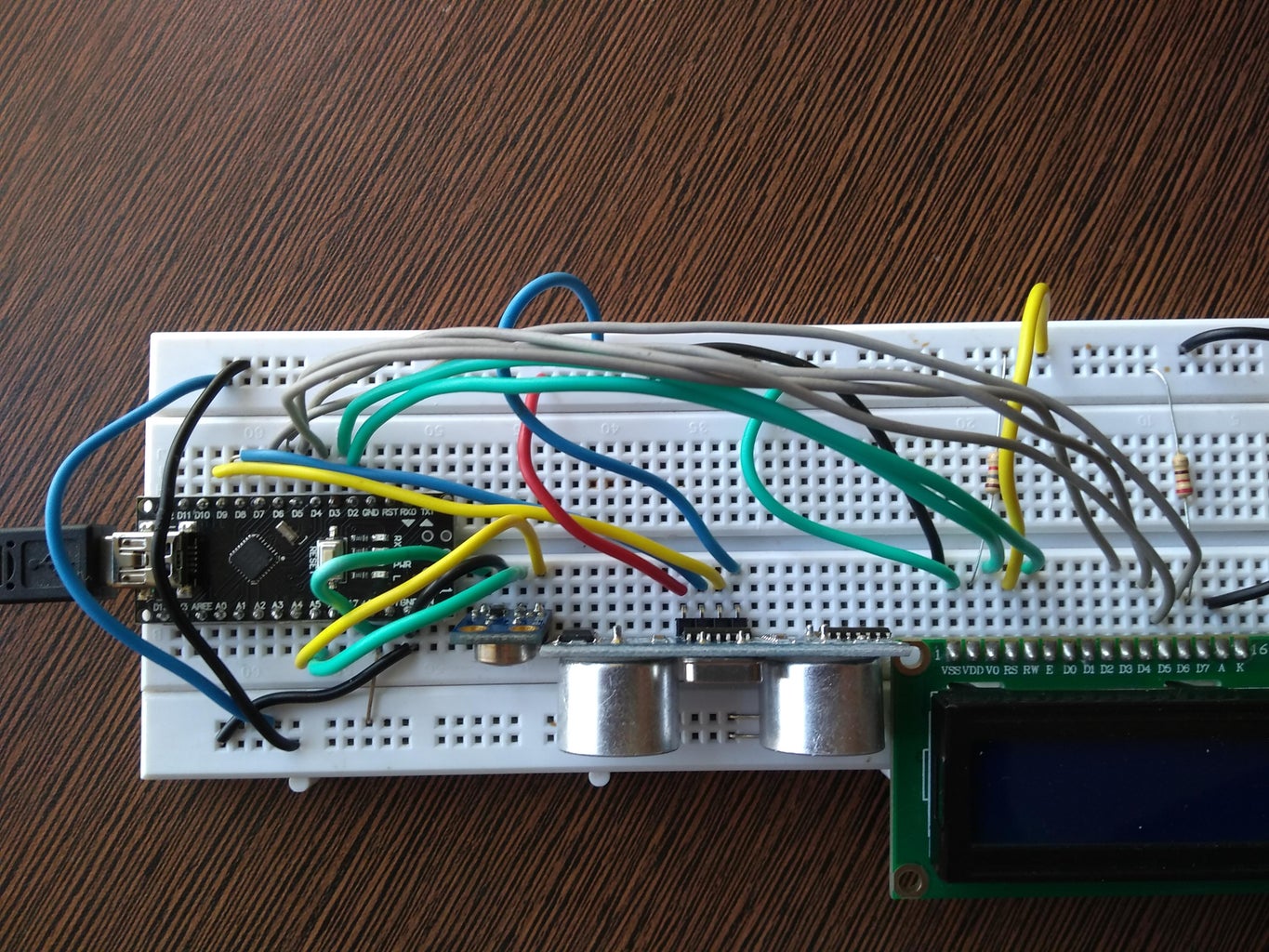
Step 5: More Images
Step 6: Code
Please find code on github:
Step 7: Deep in Project From Building
Step 8: Basics of Arduino for Reference

Participated in the
Arduino Contest 2019


