Introduction: Safety Paddle Switch
Hi Everyone,
I want to mount some power tools to my workbench and I needed a way to safely turn them on when they will be mounted on the underside.
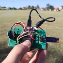
In a previous Instructable I've already made the circuit that will turn on the power tools and today I'll show you how I mounted the switch to my workbench, how I made the paddle on top of it and how it all operates.
The best thing is that in this configuration now, there is virtually no chance of me accidentally turning on any of the tools and I can very easily turn them off, even with my leg so I'll never need to let go of the piece I'm working on.
Supplies
Tools and materials needed to make this project:
- Soldering iron - https://s.click.aliexpress.com/e/_d8xmmf7
- Assorted resistors - http://s.click.aliexpress.com/e/_dSIvhPF
- Solid State Relay - http://s.click.aliexpress.com/e/_dTmBlfa
- Industrial On/Off Power Switch - http://s.click.aliexpress.com/e/_d6QWARW
- Assorted transistors (2N2907 & 2N2222) - http://s.click.aliexpress.com/e/_dZ7W6Yu
- Prototype PCBs - http://s.click.aliexpress.com/e/_dVZ8c6U
- Cordless drill - http://s.click.aliexpress.com/e/_dTPzcq8
- Belt sander - http://s.click.aliexpress.com/e/_d9bDOwk
- Wood router - http://s.click.aliexpress.com/e/_dVnVrRi
- Linseed oil - http://s.click.aliexpress.com/e/_dVHFj1W
Step 1: Select and Prepare Your Paddle Material
I've made the paddle out of a salvaged pallet board that is made out of beech wood. Beech is really strong so I knew that it will hold up to the task, although it does not need to have too much strength.
To make it look nice, I've used my belt sander to smoothen it out and then I sanded all of the edges by hand so it is easy to handle.
Step 2: Transfer Your Design
I drew a sketch of how I wanted the paddle to look and I then transferred it to the board.
At the beginning, I thought of making the paddle 17cm long but I then decided to make it longer so I can also engage it with my foot. The final dimension is 27 by 7cm.
Step 3: Cut Out the Paddle
Once I was happy with the shape, I've used various tools to first trim off the damaged part of the pallet board at the end, trim off the corners so it has a nicer shape and used my coping saw to make the cutout for where the on part of the switch be accessible.
The entire time, I kept the pallet board at full length as it was much easier that way to clamp it and work on it. Only when I rounded the edges on outside of the paddle and the edges of the switch cutout, I cut the paddle off the pallet board and also cut a small 24mm piece to act as a spacer for the hinge.
A final sanding of the edges made the whole piece nice and smooth to the touch.
Step 4: Attach the Hinge
The paddle needs to swing so I've cut a section of a piano hinge to the same length as the paddle. When selecting, I made sure to have at least two holes on each side of the hinge so I can more easily attach it to the paddle and the spacer on top.
I've first marked out the holes and predrilled the holes so I don't split the wood.
Step 5: Add the Pushing Dowel
In order for the paddle to engage the switch, I've marked out the location where the switch will be relative to the paddle and drilled a hole partially to it.
I've then added a small dowel in the hole without any glue, so it can be adjusted later if needed.
Step 6: Mount the Switch to the Workbench Leg
I've used the paddle to figure out its placement and once I was happy I removed one side of the leg in order to have better access.
This step will greatly depend on the workbench that you have.
Since the switch was originally intended to be mounted on a metal plate, I had to remove a lot of material from the back of the leg and in order to keep its strength, I've added a small piece of 3mm hardboard to the front on which I mounted the switch.
The board is then screwed in place with 4 screws from the front.
Step 7: Mount the Paddle and Install the Leg
I've determined the paddle placement by placing it on top of the switch so I can see where the dowel engages it. Once this was done, I've marked out the location and also marked positions for two holes so I can screw the paddle to the workbench leg.
With the paddle mounted to the table, I screwed in the leg to the workbench and added a coat of linseed oil to the paddle to finish it.
Step 8: Connect the Electronics
You can get all of the details for the circuit in my previous Instructable.
I used the same board here, where for the 5V power I used an old mobile phone charger that I've stripped from its case and soldered wires to the input and output terminals.
On the relay, I've added a heatsink from an old graphic card and I made sure to add plenty of thermal grease for better heat dissipation.
Everything is packaged in a plastic container that I made a hole in it to mount the SSR to the lid and have its heatsink outside. The input wire comes in and powers the 5V power supply and breaks one of the connections on the SSR output.
The neutral and ground wires continue to an extension cord splitter so I can connect more than one tool if I ever need to.
Since the push switch is outside of the box, I've added two wires to come out of the box and connect to both of the switches.
Check out all of the details about the circuit in the video below.
Step 9: Mount the Electronics
With everything packaged inside the box, I've used two small screws to mount it to the inside of the workbench and I also mounted the extension cord to it.
The input side goes through the workbench side and it will be connected to the wall power through a socket so it can be unplugged completely if there's ever a need to.
Step 10: Enjoy!
Since I don't have any other power tools yet that can mount to the workbench, I've used my disk sander to test out the circuit.
I can now be sure that I can safely turn on any tools that I can connect to the workbench and also more importantly safely turn them off.
If you liked this Instructable, be sure to check my other ones and also subscribe to my YouTube channel for more projects in the future.
Also, if you haven't watched the video of me building this paddle switch, you can check it below.
Thank you for reading!


