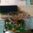
Introduction: Servo Control Using the LinkIt One
With the LinkIt One board, plenty of wirelessly connected projects are placed right at your fingertips, just waiting for you to delve into them. With the addition of servos, projects such as sound-controlled locks, indicators, and robots involving the LinkIt One are all possible.
For this project, you'll need to have the LinkIt One drivers installed already for your computer, as well as the SDK update to your Arduino IDE required to connect to the LinkIt One board. Instructions for how to do this can be found here.
Step 1: What Materials Are Needed
- Servos (However many you want to use for your project)
- LinkIt One board
- Installed Arduino IDE + Drivers/SDK
- Prototyping wires or breadboard jumper wires
- Potentiometer
- Breadboard/Protoboard
- USB cable for the LinkIt One
Step 2: Wiring Up the Servo and Potentiometer to Your LinkIt ONE
Connect the red wire of the servo either to the 5V pin on your LinkIt ONE or to the breadboard's power rail. You will need to draw power from the LinkIt ONE to the power rail if you choose to go with the second option. Next, connect the black wire of the servo to the GND pin on the LinkIt ONE or the ground rail of the breadboard.
After this, connect the white (or yellow in some cases) wire to one of the analog pins of the LinkIt ONE board. It is through this pin that the board will communicate with the servo, directing it to various positions.
Repeat this process with the potentiometer, with either leg on the right or left going to 5V and the other to GND, while the middle pin should be connected to another analog pin on the LinkIt ONE.
Step 3: Example Program for Potentiometer Control
Now that the circuit is completed, we can use some test code to control the servo.
Program begins here:
#include
Servo myservo; // create servo object to control a servo
int potpin = A0; // analog pin used to connect the potentiometer int val; // variable to read the value from the analog pin
void setup() { myservo.attach(9); // attaches the servo on pin 9 to the servo object }
void loop() { val = analogRead(potpin); // reads the value of the potentiometer (value between 0 and 1023) val = map(val, 0, 1023, 0, 180); // scale it to use it with the servo (value between 0 and 180) myservo.write(val); // sets the servo position according to the scaled value delay(15); // waits for the servo to get there }
Program ends here.
This code will allow you to control the servo just by twisting the knob of the potentiometer clockwise and counter-clockwise. For this specific program, the analog pin for the potentiometer is attached to A0 on the board. You can just change this value to match your setup, or change the wiring accordingly. The servo's input pin is connected to digital pin 9 in this example.
If you are using more than one servo, all that you have to do is copy the lines that initiate the potentiometers and servos and change the values accordingly. Copy these lines for however many servos you have. This program assumes one.
Step 4: Conclusion
Now that you have your servo(s) jittering away (they tend to do that), try making something else! Write your own program to control the servo motors and don't forget to share it with us!


