Introduction: Simple Line Follower Robot


In the previous instructable I introduced you to KeyBot. In that article I covered what KeyBot is, How to assemble it and set up the programming environment. If you haven't read that, check it out: "KeyBot: Educational Robot Kit"
In this article I want to show, how easily you can build a line follower using this kit.
Note: If you are interested in robotics and want to build your own robot car from scratch, Here is an awesome ebook which will take you through all the steps to make your own robot. Get a copy now: "Mini WiFi Robot"
To get started first you need the following material.
Supplies
- Keyestudio's KeyBot Kit. (Amazon US / Amazon EU)
- 18650 Battries. (Amazon US / Amazon EU)
- Black Electrical Tape. (Amazon US / Amazon EU)
When you have all the above items, we can get started. But first let's understand what a Line follower robot is and how it works.
Step 1: What Is a Line Follower?

Before we start first let's look into what a line follower is and how it works.
So a line follower is an autonomous robot that can detect and track a black line on white surface or vice versa. It does this using a set of IR sensors and a microcontroller. This can be classified in two processes.
1. Line Detecting.
In this process the IR sensors are used. These sensors consists of 1 IR LED and 1 photodiode each.There can be 2 sensors or an array of these sensors for more complex raouts . In Keybot, we have a Line sensor with 3 of these IR pair.
The IR LEDs keep emitting light which is then reflected on the white surfaces and received by the photodiode. Black colour absorbs most of the light and hence no/very small amount is reflected to the photodiode. Using this we can detect the black line on white surface.
2. Line Tracking.
Now that we can detect black line, all we have to do is write an algorithm that will track this line and make the robot follow it. For that we will use a microcontroller. Keybot provides us with an arduino compatible development board.
Uses.
Line followers, as the name implies just follows lines. These type of robots are used in many industries. They are used in factories to carry material/products from one place to another without human assistance.
So without wasting any more time, let's get started with building one.
Step 2: Writing the Code:


Here I assume that you have already assembled the robot, if you haven't then refer my previous instructable. We will use the Mixly block programming to build this algorithm. So make sure you have installed the software.
Now open the Mixly IDE and follow the steps below:
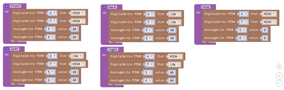
- First we have to create some functions namely: front, back, left, right and stop. These functions will move the motors. So goto the "Functions" tab and drag "do procedure" . Name the procedure "front".
- Next goto "In/out" tab and drag "DigitalWrite". Select pin "4" and set it "High", Again drag a new "DigitalWrite" and select pin "7". Set it "High".
- Now from the "In/Out" drag "AnalogWrite", Select pin "5" and set value "80". Drag another "AnalogWrite", select pin "6" and value 80.
- Similarly we need 4 more functions. Just refer to the image above and make sure you select the correct pin and set the right value.
With that been done, we now have 5 movement functions which will control the motors. Next we want to make a loop which will call these functions when the sensors are triggered.
- Goto "Control" and select "if-do" block. Drag it to the canvas and click on the small blue gear icon on it. Select "else" from the dropdown, drag and place it in the if-do block.
- Next follow the similar drag and drop to make the loop. Refer to the image above for details. Again, make sure you use the correct name and values.
Once you have made the loop, click on the arrow on the right side of the screen to pull the Code editor to take a look at the final code.
Note: If you have no prior experience with Arduino programming, you don't have to do this. The block program is fine.
Now to time to upload the code onto the control board. First connect the board to your PC using USB.
In the mixly, Select "Arduino/Genuino Uno" and select the correct Com port. Then hit Upload and wait for the code to get uploaded.
Here is the code file you can directly upload:
Attachments

Step 3: Testing:
Finally we can test how our line follower works. But first we need a track.
To make the track, take a black electrical tape (2cm or 3/4 inch). Make a track with the tape on a white surface.
Now place the robot on the track and power it on. You should see the robot follow the line straight away. But in case it doesn't, Here's what to do.
- Check the code for any mistakes.
- Make sure the batteries are fully charged.
- The sensor is plugged in properly and in the correct port. (A1,A2,A3)
- Make sure the motors are connected properly.
If the bot still give problem to track the line, Do as follows:
- Place the robot on the track as the sensors are centered on the black tape. i.e the central sensor should be on tape and the other two should be on white surface.
- You should see the two sensors on the side are active as the LEDs turn on. The LED of central sensor should be off.
- If that is not the case, use a flat head screwdriver to adjust the small pots to make the sensors as per mentioned above.
That should solve the issue and the robot should track the like.
This is just the basics of line following, you can make changes to the code and make it more complex. There are many things you can do with this method. Time to use your creativity....
That's all for this tutorial, hope you find it helpful. If you have any doubts, feel free to ask in the comment section.