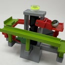
Introduction: Single Cylinder Air Engine Smaller Edition
Single Cylinder Air Engine Smaller Edition is the smaller sibling of my previous Single Cylinder Air Engine here: https://www.instructables.com/id/Single-Cylinder-.... While Single Cylinder Air Engine Smaller Edition was designed as a test platform for another design, the test video I posted on Youtube caused a few people to message me to ask for the model, so here it is. I've included a video that shows this engine in a new design I have yet to complete.
Having a smaller total displacement than my previous design, this engine runs longer on balloon power but as a trade off delivers less torque. Also, being smaller and having a crank shaft that is assembled in place requires even more fine scraping, sanding and/or filing and meticulous assembly steps to make this engine work at its peak efficiency, so be patient during the printing, preparing and assembly process.
I probably forgot a file or two or something, so if you have any questions, please feel free to ask.
Designed using Autodesk Fusion 360, sliced using Cura 2.3.1, and printed in PLA on an Ultimaker 3 Extended.
Attachments
Step 1: Print and Prepare the Parts.
I printed my parts on an Ultimaker 2+ Extended and an Ultimaker 3 Extended using .1mm vertical resolution and 100% infill.
Print two each of "Journal Crankshaft 4mm.stl" and two each of "Journal Crankshaft 10mm.stl". Print one each of the remaining parts.
"Base.stl" must be printed using supports. "Cylinder.stl" must not be printed with supports.
Prior to assembly, test fit and trim, file, sand, etc. all parts as necessary for smooth movement of moving surfaces, and tight fit for non moving surfaces. Depending on the colors you chose and your printer settings, more or less trimming, filing and/or sanding may be required. Carefully file all edges that contacted the build plate to make absolutely sure that all build plate "ooze" is removed and that all edges are smooth. I used a flat jewelers file and plenty of patience to perform this step.
Study "Assembly.stl" carefully noting the locations and positions of the various components as assembly proceeds.
Step 2: Install the Piston Rod, Piston and Valve.
Slide "Rod Piston.stl" into "Base.stl" carefully noting the orientation of the hole in "Rod Piston.stl".
Next, press "Piston.stl" onto "Rod Piston.stl" until it is exactly 28mm from the end.
Finally, slide "Valve.stl" into "Cylinder.stl", carefully noting the orientation of "Valve.stl".
Step 3: Attach the Cylinder Assembly to the Base.
Carefully position the cylinder assembly into the base assembly and press it fully into place.
When fully in position, the piston rod and valve should easily fall in and out of the assembly when tilting the assembly up and down. If not, it's time to disassemble and continue filing and sanding.
Step 4: Attach the Piston Arm to the Piston Rod.
Using "Pin Arm Piston.stl", attach "Arm Piston.stl" to "Rod Piston.stl".
Once attached, "Arm Piston.stl" should swing freely on "Rod Piston.stl".
Step 5: Attach the Valve Arm to the Valve.
Using "Pin Arm Valve.stl", attach "Arm Valve.stl" to "Valve.stl".
Once attached, "Arm Valve.stl" should swing freely on "Valve.stl".
Step 6: Assemble in Place the Piston Journal.
Assemble the piston journal in place using both "Journal Crankshaft 10mm.stl" parts.
Once assembled, the entire piston drive train should rotate freely.
Step 7: Assemble in Place the Valve Journal.
Assemble the valve journal in place using both "Journal Crankshaft 4mm.stl" parts carefully noting the position of this journal assembly with that of the piston journal assembly.
Once assembled, the entire piston and valve drive train should rotate freely.
Step 8: Attach the Wheels.
Attach "Wheel Piston.stl" to the piston journal.
Attach "Wheel Valve.stl" to the valve journal.
At this time, if you have successfully scraped, sanded and filed all parts, the entire assembly should rotate with ease.
Congratulations, and I hope you enjoy it!

Participated in the
Design Now: In Motion Contest


