

Introduction: Smart Trick-or-Treat Candy Bucket


Halloween candy buckets are good for holding candy, but you usually don't know what you've got until you get home and dump it all out. What if your bucket could recognize "treats" (your favorite candy) vs "tricks" (what you hand off to your little siblings) and react in the moment? Create the coolest candy holder in your group with this project!
If you’ve ever gone trick or treating, you know that some houses have great treats, and some well…don’t. This smart trick or treat bucket recognizes and reacts to the candy being added.
I took an existing Halloween bucket and adapted it to hold my hardware so it is still portable and stores candy. As a piece of candy enters the top of the bucket, it triggers a motion sensor and the embedded camera takes an image, which is then passed through a pre-trained machine learning model to recognize the candy and tell me if it's a "trick" or a "treat". Based on that value, either animating lights and laugh will be the reaction , or a spooky voice will say "this is not enough"!
This project uses the popular Raspberry Pi and some off-the-shelf components like a USB camera, ws2801 RGB LEDs, mini PIR, and small speaker that can all last on battery power for a full night of trick-or-treating! I used Viam to compose and program the components, collect images of the candy from the camera, train the ML model, and deploy my code when it was ready.
Follow along and read about how to make your own personalized smart candy bucket!
Supplies
1 × Raspberry Pi 4B - Any 64bit Single Board Computer running Linux should work, especially if it is supported by DietPi
1 × Haloowoo Halloween Candy Bucket with LED Colour Lights Canvas Bag with double lining
1 × NooElec 1m Addressable RGB LED Strip - ws2801 RGB LEDs
1 × MAX98357 I2S Audio Amplifier Module - Breakout board for driving speakers
1 × HiLetgo AM312 Mini PIR - Motion detection component
1 × Arducam 1080P Day & Night Vision USB Camera - Embedded camera
1 × MakerHawk 4 Ohm 3 Watt Speaker - Small but powerful embedded speaker
1 × ENEGON Portable Charger Power Bank 10000mAh
2 × 12mm Vertical Slide Switch SPDT
1 × Assorted jumper wires
1 × USB-A to power/ground cable
1 × USB-C to power/ground cable
Step 1: Access the Inner Lining of the Candy Bucket
The way to get started making is by tearing something apart!

Using some small scissors or razor knife, remove the top seam of the candy bucket lining as much as needed to stick your hand in and move around freely. You'll be placing components and running wire between the linings to hide away all the smarts!
Step 2: Create an Access Point at the Bottom of the Bucket
This is where the wires from the inner lining will reach the battery and Raspberry Pi.

The picture above shows where the bottom tear is placed to fit the wires that will be passed through.
Step 3: Place the RGB Light Strip
Electrical tape is a great resource.
The light strip may have some paper backing that can be peeled off so hot glue can be applied to the strip. That will hold it in place within the lining of the bucket. Adding some electrical tape as extra measure will ensure it stays put while continuing to maneuver inside. Make sure the end of the strip with male header pins runs through the bottom access point of the bucket. 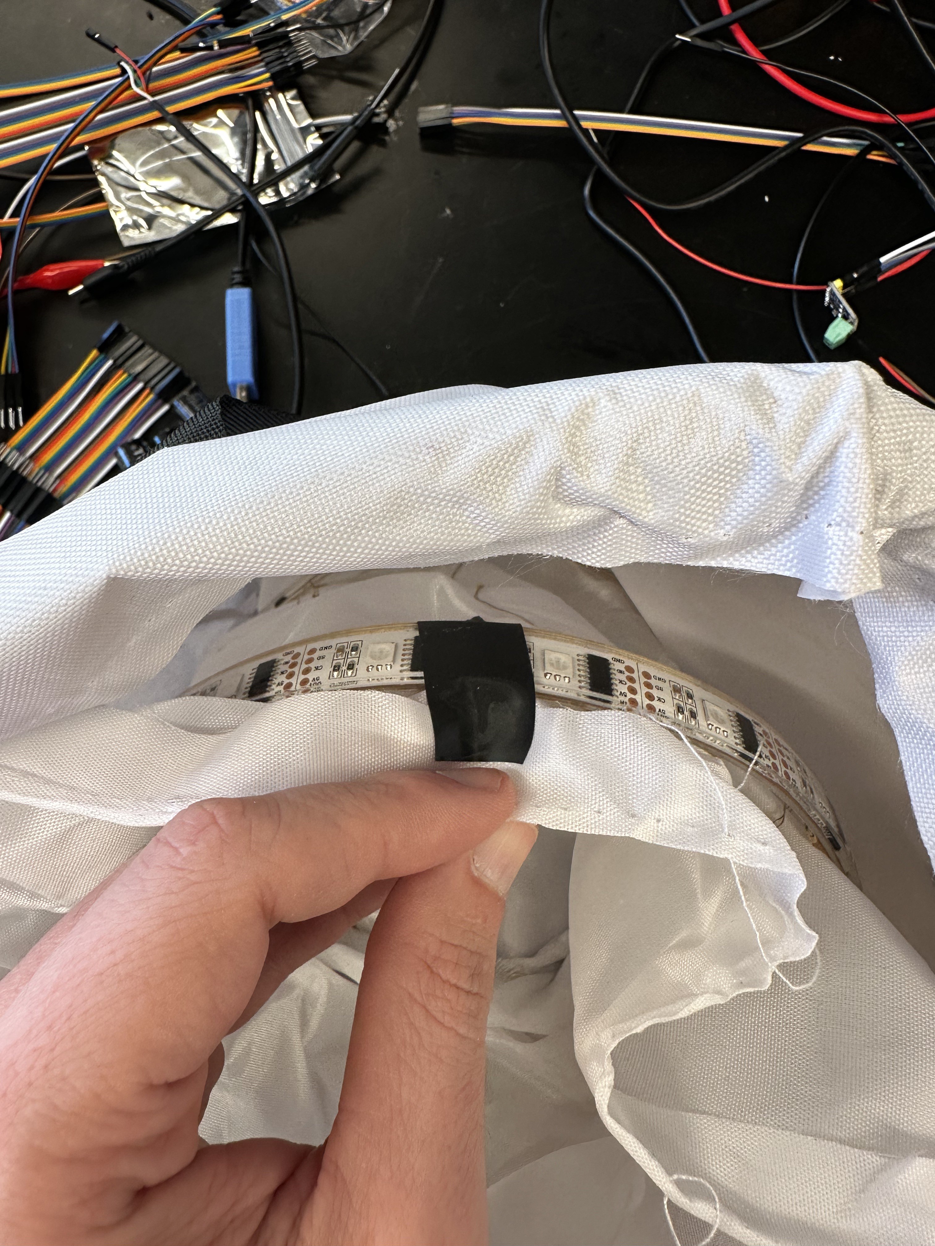
Step 4: Place the Camera
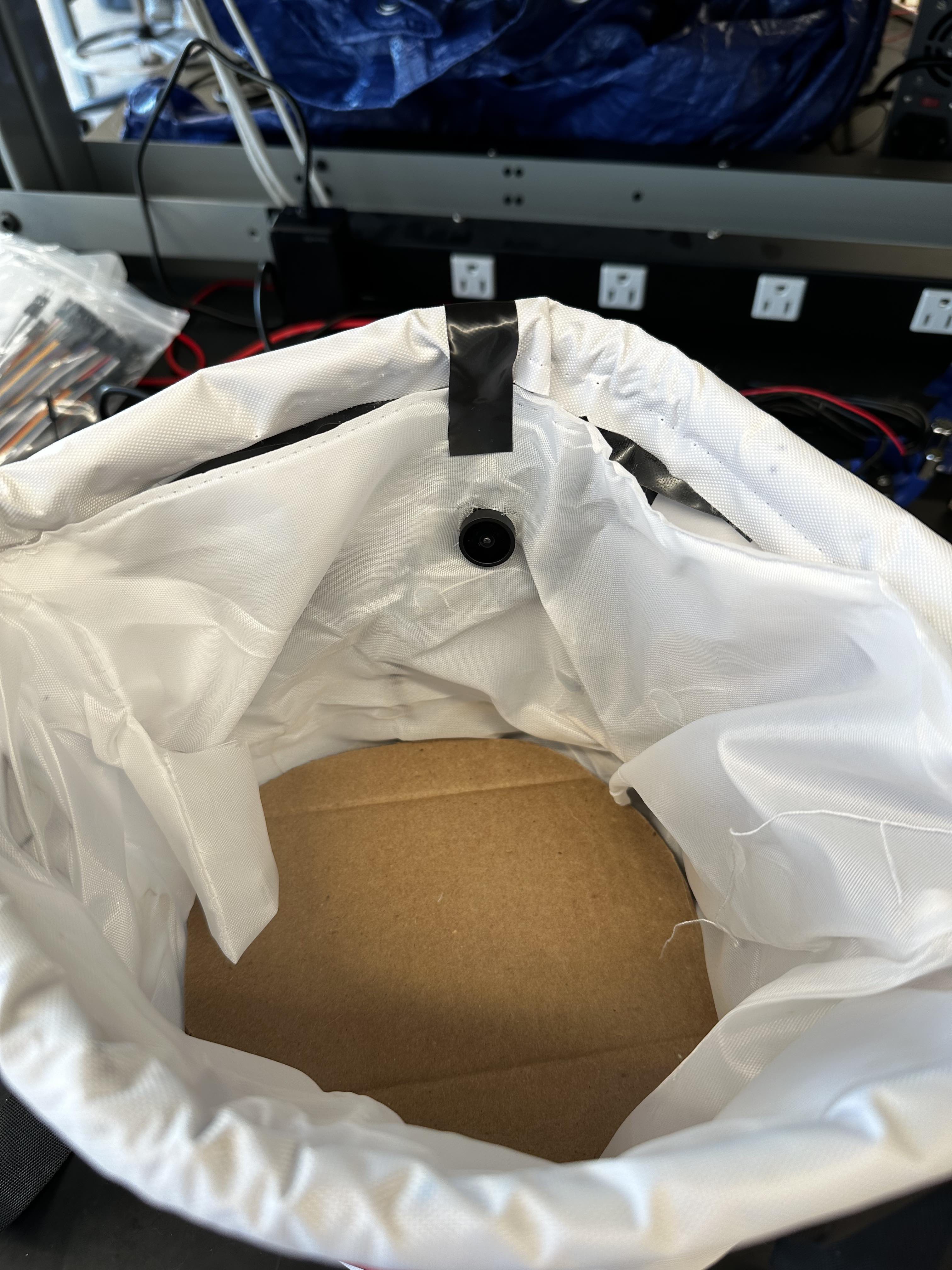
Cut a hole in the lining about a third of the way from the top of the bucket for a snug fit of the camera lens. Use more electrical tape to keep it in place before you're ready to hot glue the back of the camera to the outer lining when closing the whole thing up in a later step. Run the USB cable connected to the camera control board down to the hole in the bottom lining.
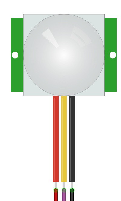
Step 5: Place the Mini PIR
For the mini PIR, I printed a housing to hide it away a little bit and keep the sensor focused on the inside of the bag. It can be mounted anywhere around the rim of the bucket, but I found about 45 degrees from the camera was good to trigger it just before the candy reaches the front of the camera.
Run jumper wire from the PIR to the opening at the bottom of the inner lining. Tape the three wires (power, data, ground) together to make it easier to push through the lining and keep it organized before connecting to the Pi in a later step.

Step 6: Place the Speaker
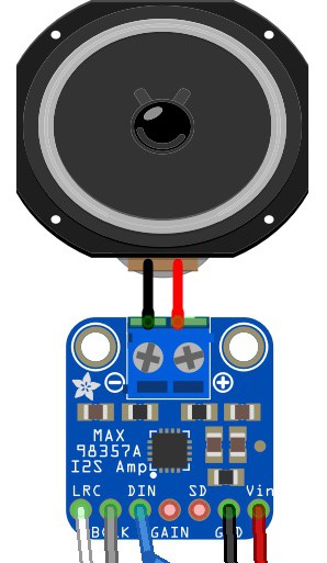
The speaker should be wired to the screw terminals on the I2S amp breakout board using a small screwdriver, tight enough to make sure they stay in place. Connect jumper wires to the bottom pin headers on the board (Left/Right Clock, Bit Clock, Data In, Ground, and Power) and place those components anywhere you'd like on the inside of the lining. The speaker is loud enough to be heard from within the lining, so it can be placed on the bottom or taped somewhere higher up. Run the jumper wires through the bottom hole of the bucket for connecting to the Pi later. Tape them together to make it easier to keep organized and push through the lining.
Step 7: Place the Switches
With two SPDT swtiches, connect two jumper wires to each: one in the middle pin and one to the right pin. The middle pin will eventually be connected to the battery and the right pin will connect to either the Pi or the RGB light strip. Place the switches near the existing fabric pocket holding the button for the string lights within the bucket (not related to the RGB light strip). There should be an existing hole to run the switch wires through to the bottom of the bucket, otherwise make one using some scissors or a razor knife.


Step 8: Wire Up the Pi, Light Strip, and Battery
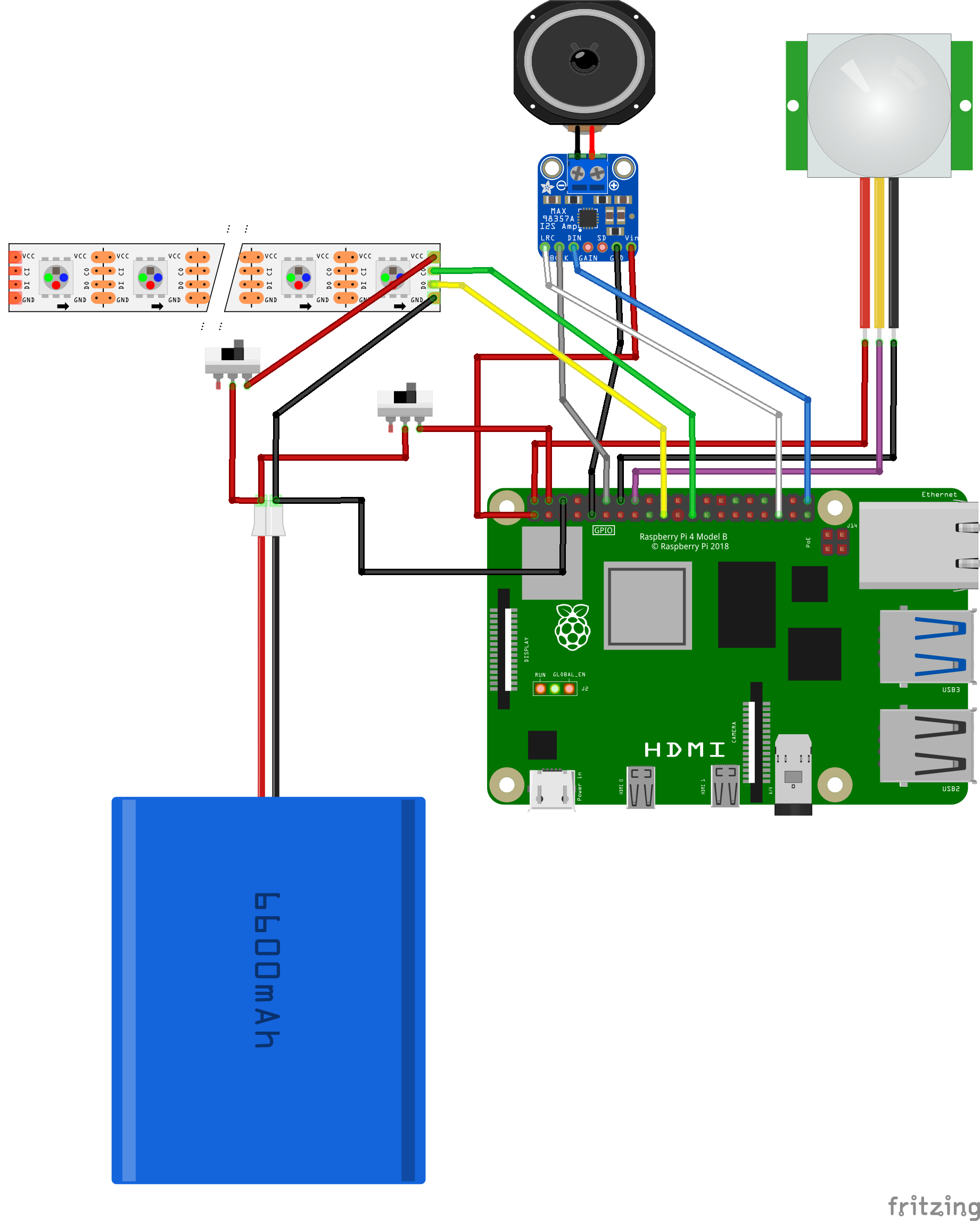
After placing the Pi and the battery on the bottom of the bag, connect the jumper wires for all the hardware components. Starting from the top of the pins on the Pi (use this diagram] to follow along if you're unfamiliar with the pinout):
Pin 1 (3v3 Power) <-> Power wire for the I2S amp breakout
Pin 2 (5V Power) <-> Power wire for the mini PIR
Pin 4 (5V Power) <-> The right pin jumper wire for one of the SPDT switches
Pin 6 (Ground) <-> Common ground wire for the battery
Pin 9 (Ground) <-> Ground wire for the I2S amp breakout
Pin 12 (PCM CLK) <-> Bit Clock (BCLK) wire for the I2S amp breakout
Pin 14 (Ground) <-> Ground Wire for the mini PIR
Pin 16 (GPIO23) <-> Data wire for the mini PIR
Pin 19 (SPI MOSI) <-> Data header pin on the RGB strip
Pin 23 (SPI SCLK) <-> Clock header pin on the RGB strip
Pin 35 (PCM FS) <-> Left/Right Clock (LRCLK) wire for the I2S amp breakout
Pin 40 (PCM DOUT) <-> Data In (DIN) wire for the I2S amp breakout
The right pin wire for the other SPDT switch should be connected to the power header pin on the RGB light strip and the ground on the strip connected to the common ground on the battery.
The middle pin wire on both switches should be connected to the power wire/connector on the battery.
Try flipping the switches to ensure power is running to the RGB strip and the PI correctly. If nothing happens, toggle the switch back the original position before attempting to debug any issues.
Step 9: Set Up the Raspberry Pi
With all the hardware components in place, you can start working on the software piece. Although this project uses a Raspberry Pi 4, any single board computer (SBC) that supports general purpose input/output (GPIO) with PCM/I2S pins and runs 64 bit Linux should be able to work as well. Having wireless network (Wi-Fi) is handy for iterating on the software, it is not necessary when using the completed project out in the world. I chose DietPi as the operating system for the Pi because it is very minimal while providing a nice command-line user experience to configure various parts of the system; it also supports many SBCs, so the instructions will stay largely the same.
Follow the DietPi documentation for flashing an SD card to install on the Pi. In the GitHub repository for this project, I have included an example `dietpi.txt` configuration file to help with the automatic base installation on first boot of the SBC. This will help include expected software like Python3, RPI-GPIO, OpenSSH, as well as connect to your Wi-Fi network and set a static IP address for easy discovery. Once you're able to ssh and login to DietPi, then continue to the next step.
Step 10: Install Viam
Viam is being used on this project to easily configure all of our hardware, train the machine learning model, and monitor the project for any issues along the way. You can connect the Pi to the Viam platform by installing `viam-server` onto the device following the Viam documentation. Once you've followed all those steps, you should have created a new robot in the Viam app and see it live:
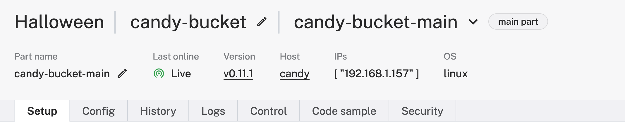
I called my robot "candy-bucket" in a location called "Halloween", but you can name it whatever you like.
Step 11: Configure Components
On the "Config" tab in the Viam app, you can add components that represent the hardware we have connected in the candy bucket; starting with the SBC:

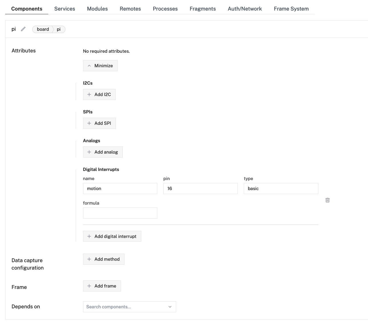
I called the board "pi" since that's what I'm using but it can be called anything. The code in the linked GitHub repo uses environment variables in a `.env` file to configure the program to use the names set in the Viam app. I have also configured a digital interrupt for the mini PIR called "motion" to help inform the code when something triggers the motion sensor. This is more efficient and reliable than constantly checking the state of the pin to see if it has changed. Be sure to hit the "Save config" button anytime changes are made to the components.
Next we have the camera:
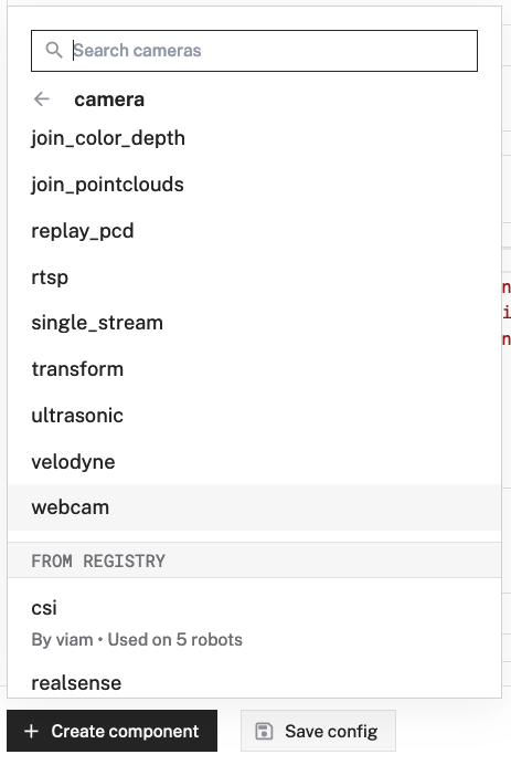

Because the Arducam component connects over USB, it acts like a webcam to the Pi. I called the component "arducam" and viam-server automatically discovers the "video path" for the connected device, so no additional configuration is needed!
The final component configuration is the RGB LED lights:

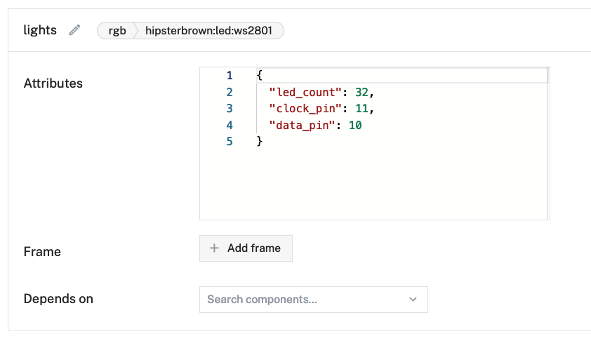
This component is enabled through a custom modular resource that I created and published to the Viam registry to allow other Viam-powered machines to control RGB LEDs. It requires three configuration attributes: the number of LEDs on the strip, the clock GPIO pin, and the data GPIO pin. Although the physical pin numbers on the device are 23 and 19 (respectively), the GPIO numbers are 11 and 10 when referencing the pinout diagram.
After hitting "Save config", you should be able to navigate to the "Control" tab to view the board and camera controls:

If you wave your hand in front of the motion sensor a few times, you should see that value next to the "motion" name for the digital interrupt start to increase.

Here you can see a live view of the camera streamed from the candy bucket where it is mounted!
With these components confirmed working, you can configure services in the next step to help with audio, data capture, and machine learning!
Step 12: Configure Services
Services are built-in software packages that make it easier to add complex capabilities to your smart machine. These can be configured on the "Services" tab next to the "Components" tab in the Viam app.
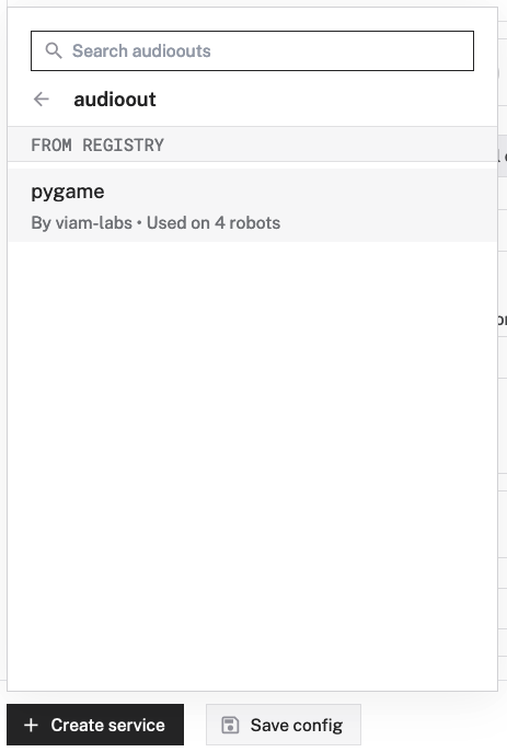
The first service is the "audioout" custom resource to play audio files through the I2S amp and speaker:
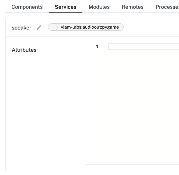
It does not require any configuration in the Viam app. Instead, we will be using the `dietpi-config` command line tool to configure the `rpi-dac` audio device on the board in a later step.
The next and last service, for now, is the data capture service to help gather images to train the machine learning model:
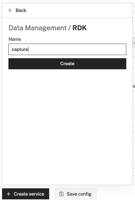
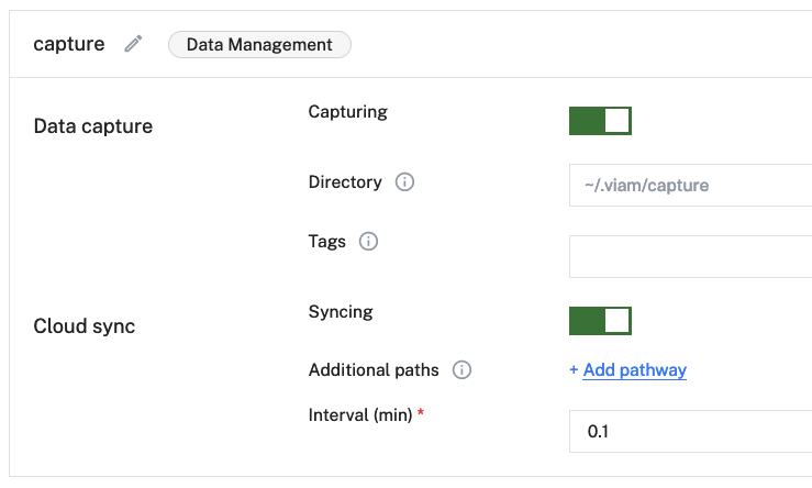
It should be capturing and syncing by default, if not then enable those toggles. You can set a quick interval of "0.1" to get real time results while actively gathering images from the camera, which you'll configure next. Make sure to hit "Save config" before switching to the "Components" tab.
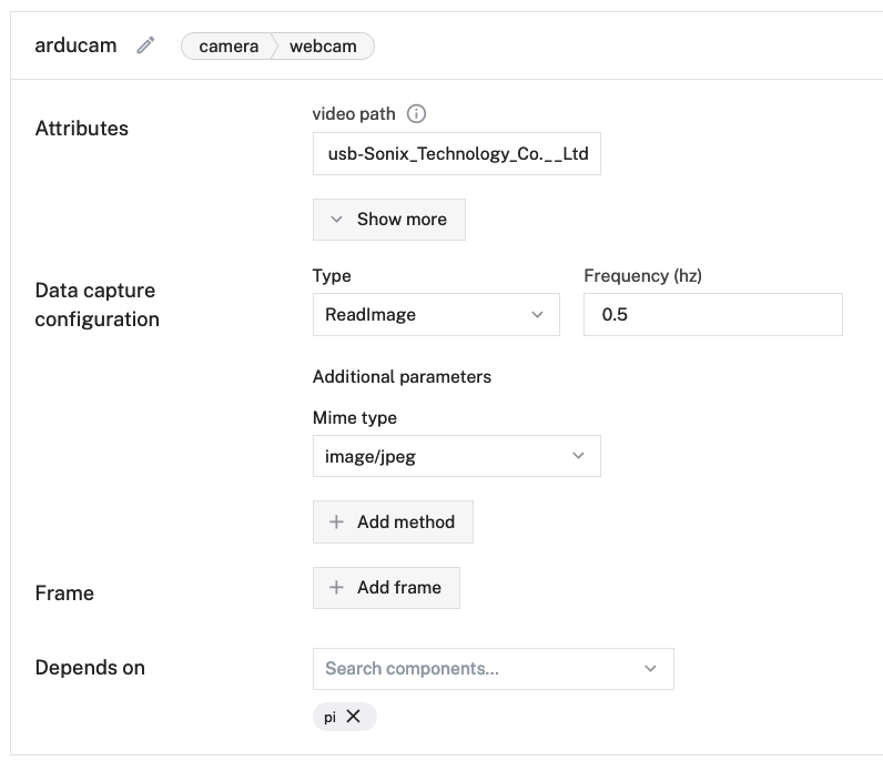
On the "Components" tab, you'll configure component data capture on the "arducam" component to capture a JPEG image every half a second. Once you hit "Save config", you can open the "Data" view in the app to see the images start syncing with Viam cloud. You may need to refresh the page every so often to see new images.
Now you can start holding different candies in front of the camera from all sorts of angles and orientations to get a diverse set of data for the machine learning model. I found it helpful to enable "Picture-in-Picture" on the live camera view from the "Control" tab of my machine in another tab while viewing the "Data" syncing.

I didn't gather 31,000+ images for this project as the screenshot above may suggest; it is displaying a count across my whole org. I didn't gather a few hundred though, most of which were used to train the model.
Once you've gathered all the images you need, make sure to disable data capture in the camera component config and hit "Save config".
Step 13: Train the Model
This part may get a bit tedious but you can find a rhythm and start to have fun providing your own opinions into this candy detector model!
You'll draw and label bounding boxes around the images of candy you want to use to train the model.


Create two new labels: "trick" and "treat". For each candy type, choose a label and draw a box around the parts that most uniquely identify it. There should be at least 10 labeled images for each label to train the model, but the more images in the sample, the smarter and more accurate the model will be.
Once you're ready to train the model, select "trick" and "treat" in the "Bounding box labels" filter field on the left side of the page and hit "Search" to show all the labeled images. Then click on the "Train model" button in the upper right to fill out the form with information about the type of model and included labels:
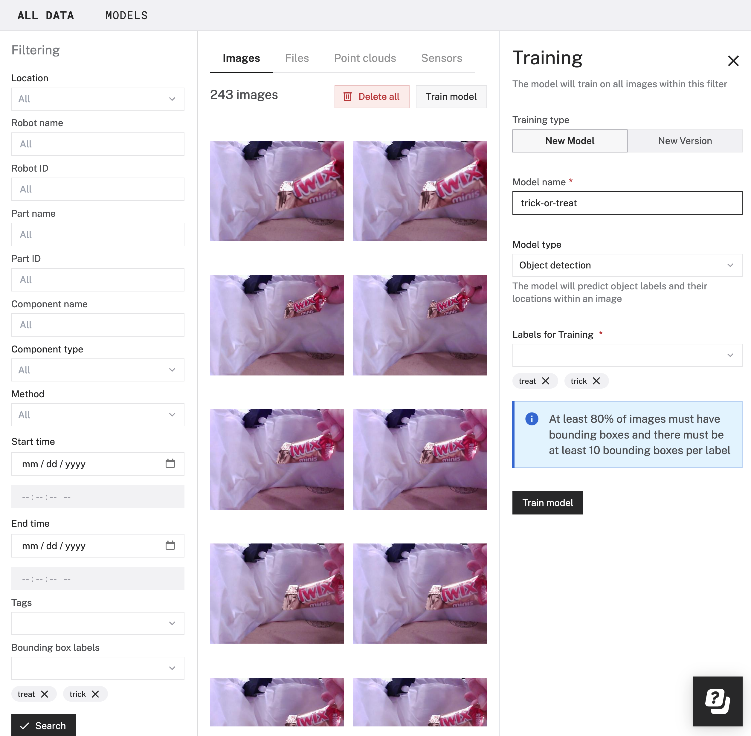
Name the model whatever you'd like and select "Object detection" for the model type. Then select the "trick" and "trick" labels to use for training before clicking the "Train model" button below the fields to kick off the training job. This should take you to the "Models" view and display your new model name under the "Training" section. This will take about 10 minutes to complete and shows the final model under the "Models" section on the page.
Step 14: Deploy the Model and Configure Vision Service
With the trained model ready, you can deploy it to the Pi by configuring the ML Model service under the "Services" tab of the machine configuration:
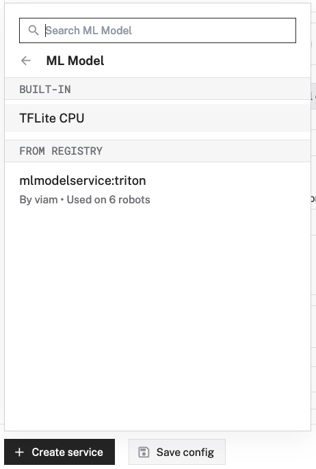
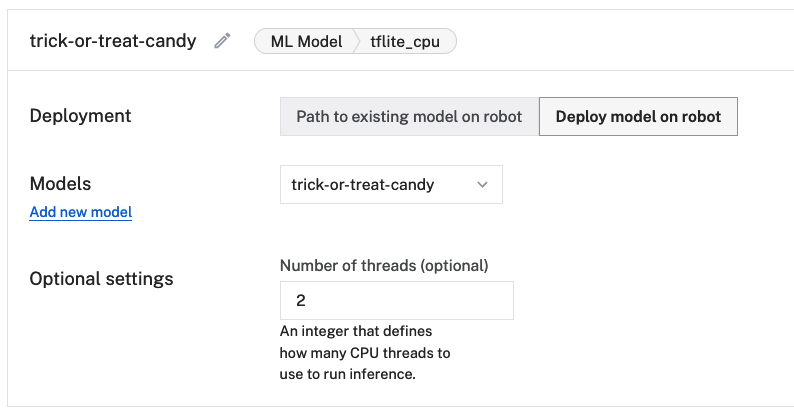
This will default to "Path to existing model on robot", so you should select "Deploy model on robot" and select the newly trained model from the "Models" list. The number of threads will default to 1, which should work fine. I set it to 2 for improved performance at the cost of CPU usages. Feel free to experiment!
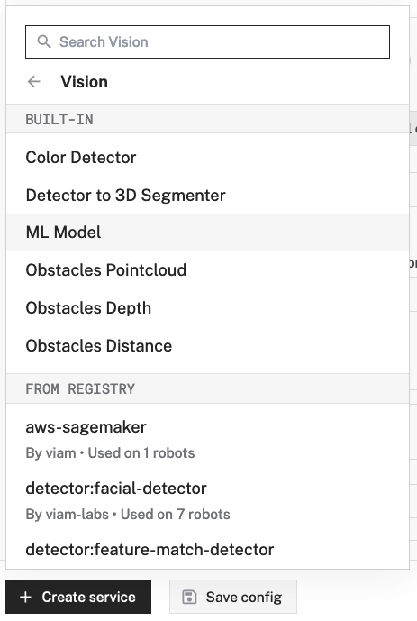
To use the model to detect candy from the camera, you'll need to configure the vision service for object detection:
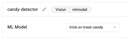
The only configuration required is selecting the ML Model service to associate with the vision service. After saving this new configuration, you can preview the working implementation by configuring a transform camera component in the "Components" tab:
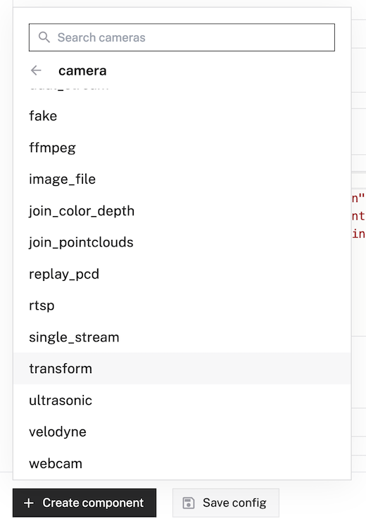

Once that configuration has been saved, you should be able to switch to the "Control" tab and see the "candy-camera" available to view. Hold up some candy to the mounted camera and see what it detects:
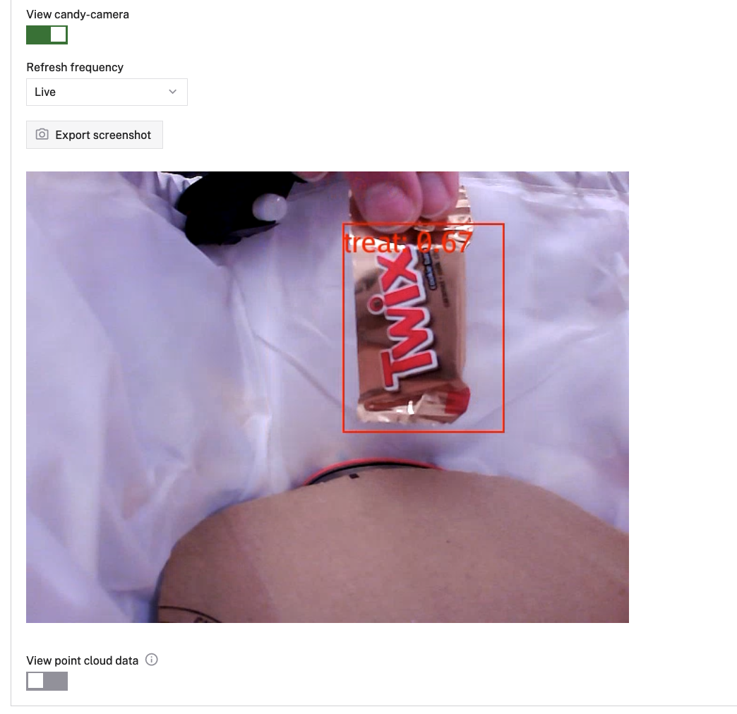
If you are happy with the performance of the model, then move along to the next step. Otherwise, if you want to increase the confidence and accuracy, you can add more labeled images to the training set and train a new version of the model to automatically deploy to the Pi.
Step 15: Configure Device Audio
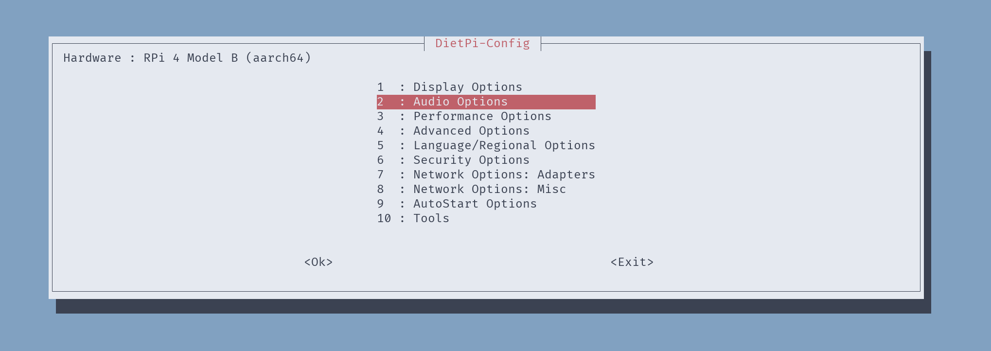
While ssh'd into the Pi, you can configure it to use the expected audio device to drive the I2S amp and speaker with the `dietpi-config` command line tool:

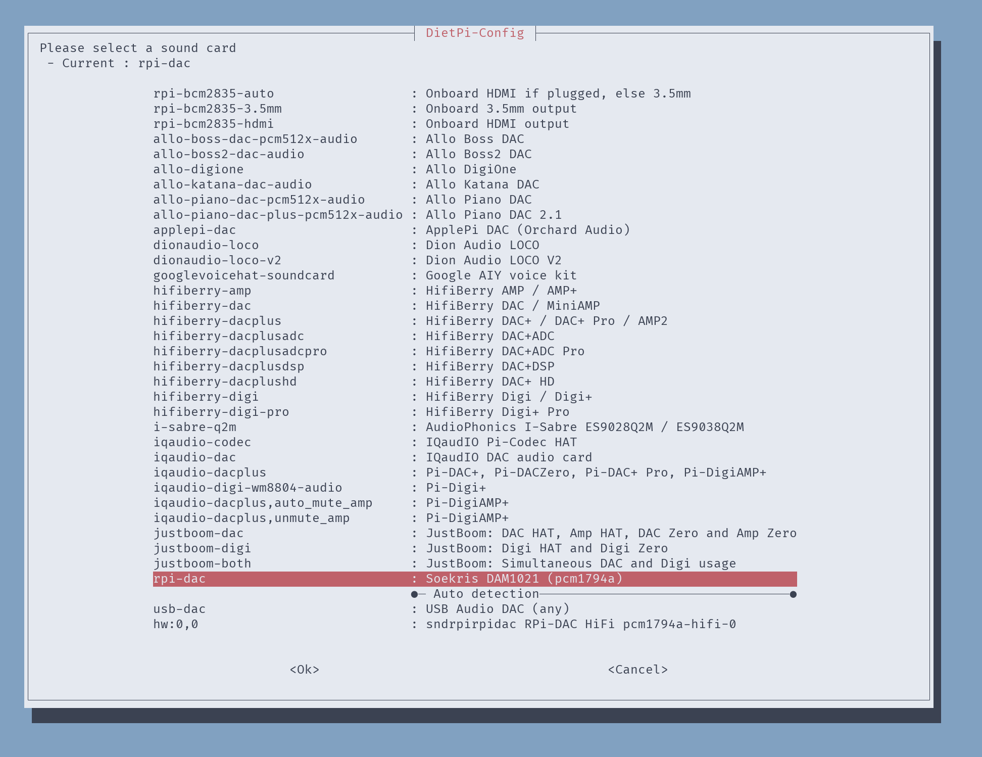
After selecting `rpi-dac`, hitting "<Ok>", and hitting "<Exit>" until you leave the `dietpi-config` view entirely, you will be prompted to reboot the Pi due to the audio driver changes. Hit "<Ok>", the device will reboot, and you will lose your ssh connection until it is back online.
Once you've created the ssh connection again, you can test the changes using the `speaker-test` command line tool:
speaker-test -c2
You should hear periodic bits of static noise coming from the speaker with feedback displaying in the command line.
Step 16: Bring It All Together With Some Code!
I wrote some code using the Python SDK for Viam to run on the Pi. It accomplishes the following:
- initializes a `CandyBucket` class that holds all the logic for our candy bucket
- reads in configuration values from the `.env` file in the repo to connect to Viam and create the component classes based on the name from the Viam app config
- runs a startup "trick or treat" audio file with some light animation to indicate it is ready to start looking for candy
- creates two background tasks:
- one captures an image when the motion sensor is triggered and adds it to a queue
- the other waits for images to appear in the queue to detect candy using the vision service and activate lights & sounds based on whether it detects a trick or treat.
The repo includes the royalty-free sound effect files along with the code and project configuration files.
To run the code automatically when viam-server starts up, we'll configure a process that executes the `run.sh` file in the repo.
Clone the repository onto the device while connected via ssh into a directory called robot:
git clone https://github.com/HipsterBrown/viam-candy-bucket.git robot
If you forget to add the `robot` add the end of the command, it will create a directory called `viam-candy-bucket` which will work but should be remembered when configuring the process in the Viam app. In the directory, rename the `.env.example` file to `.env` and fill in the values for each variable using a text editor like nano or vi
mv .env.example .env && vi .env
You can find the robot location and secret under the "Code sample" tab in the Viam app.
Go into the Viam app and configure a new process:

I called the process `main` and set the executable as `/usr/bin/bash` since it will be running a Bash script, with the argument of `run.sh` and the working directory matching the path to the code directory cloned onto the computer.
After hitting "Save config", check the logs to see the new process starting up and the candy bucket will begin to come to life!
When you are ready to go trick-or-treating, you'll just need to flip those two switches in the bucket and it will be ready to go in a minute or two!
Step 17: Next Steps
After successfully completing this project, you could iterate upon and extend it in a few ways:
- save the record of each trick or treat to a local database file like SQLite and sync it to Viam when back online to analyze your haul
- create separate compartments in the candy bucket to sort the candy when it is dropped in
- personalize the machine learning model to detect other aspects of the candy, like containing nuts for those who are allergic
If you create your own smart trick-or-treat bucket, please share it in a comment or join the Viam discord to share it with the rest of the Viam makers and hackers.
Happy Halloween!

Participated in the
Halloween Contest

![Tim's Mechanical Spider Leg [LU9685-20CU]](https://content.instructables.com/FFB/5R4I/LVKZ6G6R/FFB5R4ILVKZ6G6R.png?auto=webp&crop=1.2%3A1&frame=1&width=306)


