

Introduction: Speech Recognition With an Arduino Nano


I was desperate for something to read during lockdown and found in my bookcase an IEEE report on Speech Recognition from the late 1970s. Could an Arduino Nano do the same as a computer from that era?
How does a Nano compare with back then? A Nano has 2KB RAM, 32KB program ROM and runs at about 10 MIPS (depending on the instruction mix). The sort of minicomputer people were using back then ran at 0.5 to 8 MIPS and had, say, 2K to 32K of memory split between program and data. Most groups had a PDP-8 or PDP-11. One group had a huge IBM-360 with 128kB but under 1MIPS. Another group had re-purposed a Univac missile fire control system running at 1MIPS.
So a Nano is in the right ballpark for simple speech recognition but why bother? Other speech recognition projects exist but either require a web connection and that you send all your private conversations to Amazon or Google; or they require a larger computer like a Raspberry Pi. Clearly, a Nano isn't going to be as good as those. Can it do anything useful at all?
The hard problem of speech recognition is continuous speech by any person using a huge vocabulary. At the other end of the scale is a single speaker saying single words from a small vocabulary. That's what I'm going to attempt.
What use is that? Perhaps you want a head-mounted multimeter or a tiny ear-mounted mobile phone with no screen or keyboard. Any sort of hands-free display could benefit from simple voice commands. Or what about a remote-control robot? An MP3 player while jogging? There are lots of places where a dozen command words could be useful. If you search Instructables for "Alexa" or "Siri", you'll find around 200 projects - many of them could benefit from not requiring an internet connection. Then you could add speech output using, for instance, the Talkie library.
Did it work? Well, more or less. Under ideal conditions I was getting 90% to 95% correct recognition which is roughly what people were getting in the 1970s. Maybe you can improve my code and do better. This an "experimental" project. It's something for you to work on and improve. It's not something that you can just build and it will work first time.
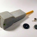
For this project, you will need an Arduino Nano (or Uno or Mini or similar so long as it uses a 16MHz ATmega328), a microphone and an amplifier for the microphone. I chose the MAX9814 microphone amplifier as it has automatic gain control.
Step 1: Hardware


You'll need an Arduino Nano. I'm assume you already know how to program an Arduino - if not there are lots of Instructables tutorials.
Search eBay for a "MAX9814" module - mine cost £1.55 plus postage. A MAX9814 includes a microphone amplifier and an AGC (Automatic Gain Control). If you can't wait for delivery and want to make your own, see the next Step.
The MAX9814 module has 4 pins labelled
- GND 0V
- VDD 5V
- GAIN
- OUT to analogue pin of Nano
- AR
The A/R pin controls the "Attack and Release Ratio" of the automatic gain control:
- A/R = GND: Attack/Release Ratio is 1:500
- A/R = VDD: Attack/Release Ratio is 1:2000
- A/R = Unconnected: Attack/Release Ratio is 1:4000
The actual timing of the attack and release is set by a capacitor on the module.
- attack time = 2.4 * C
(time in mS, C in uF)
The Gain pin controls the gain of the AGC:
- GAIN = GND, gain set to 50dB.
- GAIN = VDD, gain set to 40dB.
- GAIN = Unconnected, uncompressed gain set to 60dB.
In the circuit shown above, I have left A/R unconnected. The Gain is connected to VDD which is the lowest gain. You could connect them to digital pins of the Arduino so you can control them in software: for "unconnected", set the pin to input.
I attached the microphone and MAX9814 module onto a "microphone boom" to the side of my mouth and had a shielded cable to the Arduino on my desk. The microphone should be to one side of your mouth to avoid "popping" with plosives (p, t k) or other breath noises.
I found a gain of 40dB gave the best signal-to-noise ratio with the microphone on a boom near my mouth. With higher gains, background noise is amplified too much; when there was speech, the AGC reduced the speech signal to reasonable level but when you stopped speaking, the noise slowly returned.
The sound signal from the module is centred around 1.25V and the signal goes from 0V to 2.5V. The Arduino ADC has 10 bits so the numeric value goes from 0 to 1023. I used the 3.3V output of the Nano as the analogue reference voltage so 0 to 1023 means 0V to 3.3V.
You could connect the module directly to one of the ADC input pins but in the diagram above I have included a simple RC high-pass filter. It means that the lower frequencies of speech (below 1.4kHz) are de-emphasised. The spectrum is more flat and we can use integer arithmetic more effectively. By removing low frequencies, the amplifier and ADC are less likely to clip. There are many discussions of pre-emphasis in speech recognition, for instance this one. Because the module is AC-coupled, two resistors are used to centre the ADC input around 1.65V.
Make sure the ADC pin you connect the op-amp to matches the one defined in the sketch. You will find the declaration of the pin near the start of the sketch:
const int AUDIO_IN = A7;
Step 2: Using Your Own Op-amp


If you can't wait for delivery of a MAX9814 module and you already have a lot of electronic Stuff then you probably have an electret microphone and an op-amp. I used an LM358.
An LM358 is a pretty poor op-amp. It is certainly not "low noise" and its output can only get within 1.5V of Vcc. But it will run at 5V and is good enough for this project.
The circuit I used is shown above. It's nothing special, you will find lots of others if you search the web. The overall gain is around 200. That brings the output signal into the right range if you use a boom microphone near your mouth. C1 and R4 act as a high pass filter with a gentle roll-off below 1.5kHz.
The positive input of the op-amps (and hence the output) is at half way between 0V and 3.3V. I'm using the Nano ADC with 3.3V as Vref so the LM358 output will swing over the right range. The 3.3V output produced by the Nano is fairly noisy so needs DC4 and DC6 as decoupling capacitors.
The LM358 is powered from the 5V output of the Nano. The Nano's 5V pin has a lot of noise so it is smoothed by R3, DC3, DC5.
That smoothed 5V is filtered even further by R1, DC1, DC2 and acts as a bias supply for the microphone through R2.
Make sure the ADC pin you connect the op-amp to matches the one defined in the sketch. You will find the declaration of the pin near the start of the sketch:
const int AUDIO_IN = A7;
Step 3: Collecting the Data

The standard way of using an Arduino Nano ADC is to call analogRead() but analogRead() is rather slow. It initialises the ADC and chooses the correct input pin. Then it starts the conversion and waits until the conversion is complete. All that takes around 100uS. We would prefer to be doing other things while the ADC is waiting for the conversion so I do it differently.
In Setup() I use the standard Arduino library code to initialise the ADC:
analogReference(EXTERNAL);
analogRead(AUDIO_IN);
The reference voltage for the ADC is set to the ARef pin and ARef is connected to the 3.3V pin. By calling analogRead() once, we get the Arduino library to set up the ADC.
In the main loop, to start a conversion we set the ADSC bit (ADC Start Conversion). This tells ADC to start the conversion. The Arduino library has put the ADC into single conversion mode so we need to set ADSC to start each conversion.
The ADIF bit (ADC Interrupt Flag) is set once a conversion is complete. That means we can do something else while the ADC is busy. Surprisingly, we clear ADIF by setting it to 1. The ADIE bit (ADC Interrupt Enable) has been cleared by the Arduino library so no actual interrupt happens - we just use the Interrupt Flag to check when the ADC conversion is finished.
The 10-bit result of the ADC conversion is read by reading the 8-bit ADCL register then the ADCH resgister. When you read ADCL, the value in ADCH is frozen until you read it too. It's done that way to ensure that you don't mix up low and high bytes from different samples. You must read ADCL and ADCH in the correct order.
The complete code is
while (true) {
  while (!getBit(ADCSRA, ADIF)) ; // wait for ADC
  byte val1 = ADCL;
  byte val2 = ADCH;
  bitSet(ADCSRA, ADIF); // clear the flag
  bitSet(ADCSRA, ADSC); // start ADC conversion
  int val = val1;
  val += val2 << 8;
     ... process the sample in val
}
The "process the sample" code is executed while the next ADC conversion is happening.
The voltage from the amplifier will be centered around 512. For our signal processing, we want it centred around 0. So we subtract the running mean of the incoming value from val.
static int zero = 512;
if (val < zero)
  zero--; else
  zero++;
val = val - zero;
The speechrecog0.ino sketch tests the ADC. It can collect samples at around 9ksps. The sketch can send the values to the PC over the serial line but serial transmission slows it down to around 1100sps (at 57600baud). If you click the Tools Serial Plotter command in the Arduino IDE you'll get an "oscilloscope" display of your speech. It's a good test of whether your hardware is working.
Attachments

Step 4: Overall Software System

The overall software system is slightly complicated. Training is done on a PC but the trained system runs entirely on an Arduino.
The Arduino sends sample utterances to a PC and the PC calculates the utterance templates. The PC exports the templates as a .h file which is compiled into a sketch. The sketch can then recognise the utterances without being connected to a PC.
The SpeechRecog1.exe Windows program calculates digital filter coefficients. The digital filter coefficients are exported as the Coeffs.h file.
The speechrecog1.ino sketch (download: step 7) is compiled using those coefficients.
The speechrecog1.ino sketch gets sample utterances and sends them to the PC.
On the PC, SpeechRecog1.exe calculates the templates whch will recognise those utterances.
SpeechRecog1.exe calculates the templates whch will recognise those utterances.
Optionally, SpeechRecog1.exe collects more utterances for testing. It tests the templates using those utterances.
The templates are exported as the Templates.h file.
The speechrecog2.ino sketch (download: step 10) is compiled using the Templates.h file and the Coeffs.h file.
The speechrecog2.ino sketch uses the templates to recognise utterances.
The following Steps describe each of those parts in more detail.
Step 5: Frequency Band Filters

A typical word - an "utterance" - might last a second. A Nano has only 2k bytes of RAM so we can't store all the samples of the utterance and analyse them slowly. We must do much of the analysis in real-time as the samples arrive.
Speech recognition generally starts by measuring the "energy" in different frequency bands - i.e. the amplitude. So the first stage is to pass the input through different bandpass filters.
The most popular way of filtering the data is by performing a Fourier transform on the input to obtain its spectrum. An Arduino Nano doesn't have sufficient computing power to calculate a Fourier transform as the samples arrive. (A Nano can just manage to calculate Fourier transforms but not quickly enough.)
A more appropriate way of dividing the data into bands is by using digital filters. A digital filter performs some sort of simple maths on the previous N input samples and maybe the previous N filter-output samples to calculate the next output value of the filter. The diagram above shows a typical filter. In C we would calculate it as:
y[n] = a0*x[n] + a1*x[n-1] + a2*x[n-2] + b1*y[n-1] + b2*y[n-2]
where x[n] is an input sample value and y[n] is an output value. x[n-1], y[n-2], etc. are previous values.
The program has stored the previous 2 input values and the previous 2 output values. Because it has stored 2 of each values it is known as a second order filter.
If the output depends only on the previous input values then it is called a “Finite Impulse Response” filter: "FIR" (b0 and b1 are set to zero in the above diagram). If the output also depends only on previous output values then it is an “Infinite Impulse Response” filter: "IIR". (An "FIR" is sometimes called a "non-recursive filter". An "IIR" is a "recursive filter".)
For a bandpass filter, the order of the filter determines how steeply the filter rolls-off above and below the pass frequency. The higher the order the more control you have over the filter's response curve. Clearly, the higher the order the more coeficients you need and the more maths you have to do per sample.
An FIR filter requires more coefficients and more maths to get the same response curve as an IIR filter. But an IIR filter is less stable. It's easier to get the maths wrong for an IIR filter so that he output goes crazy or gets stuck. That's particularly true when you're using integer arithmetic as we'll be doing on the Nano.
It's hard to find a definitive value for how fast a Nano can perform addition and multiplication. It depends on how you measure it: do you include fetching and storing the values for instance. 8-bit addition takes 0.4 to 0.9 uS. Multiplication takes around 50% longer. 16-bit addition or multiplication takes around twice that (as you'd expect). And 32-bit addition or multiplication takes around 5 times the single-byte time.
Division amd floating-point arithmetic takes very much longer as they're done in software.
Let's say we want a sample rate of 8000sps, that's 125uS per sample. With 4 frequency bands that's 31uS per sample per band. We also have to collect the data from the ADC, calculate the amplitude of the bands and store the results in an array. As a result, we're limited to maybe a dozen arithmetc operations per sample. We can't afford more than a second order IIR filter.
Step 6: Calculating the Coefficients

A popular digital filter is the biquad - a second order IIR filter. There's a good discussion here.
Clearly the trick for any digital filter is finding the right coefficient values. Here is an online filter calculator.
We want, say, four bandpass filters. The coefficients for a bandpass biquad filter are
K = tan(pi * f/sps);
norm = 1 / (1 + K / Q + K * K);
a0 = K / Q * norm;
a1 = 0;
a2 = -a0;
b1 = 2 * (K * K - 1) * norm;
b2 = (1 - K / Q + K * K) * norm;
where
- f is the centre frequency of the band
- sps is the sample rate
- Q is the "Q-factor" which is 1 / (the width of the band)
We can ignore a1 as it is zero. a2 is just -a0 which simplifies our calculations.
The Q value depends on how far apart the bands are. If there are lots of bands close together then you don't want them to overlap and Q should be bigger. If the bands are far apart, you don't want Q so big there are gaps between them. For a bandpass filter, Q= fcenter/ (fmax - fmin). I found something under Q=2 is about right. With a biquad filter, if Q is too large, the filter becomes unstable.
By re-arranging the equations we can calculate the filter as:
L1 = -b1*pd-b2*ppd+input;
output = a0*(L1-ppd);
ppd = pd;
pd = L1;
You can see typical filter responses in the spectrum above.
Vowels are distinuished by their formants. A formant is a peak in the energy of the spectrum and a vowel is recognised by the relative sizes and frequencies of the first two or three formants. The first male formant frequency varies between 250Hz and 850Hz. the second formant is 600Hz to 2500Hz. Women's formants are 15% higher and children around 35% higher. Of course, there are big individual differences.
With only 4 frequency bands, we can't hope to calculate formant frequencies but they will affect the energy in the different bands. The bands you choose will depend on the speaker - presumably yourself. Because this system is for recognising a single speaker's voice, it should be tuned to that speaker.
If you want to practice filtering utterances, there are sample spoken digits in the Jakobovski free spoken digit dataset.
The coefficients can be calculated on a PC but the actual filter itself runs on the Arduino using integer arithmetic. The coefficients are real numbers in the range 0..2 so they are multiplied by 0x10000 and converted to integers. The ADC output is in the range 0..1023, so the Arduino does the appropriate shifting to get the output from the filter back into the same range. The filter input and output values are stored as 16-bit ints but some of the maths must be done using 32-bit ints to avoid problems with overflow.
So we now have the "energy" (i.e. amplitude) of 4 frequency bands. I add a fifth "band" for the Zero Crossing Rate - the "ZCR".
The ZCR is simply how often the signal crosses zero volts. It's a very good way to spot frictives and non-voiced labials such as s, sh, th, t, k, etc. You should use a little hysteresis which calculating ZCR so as not to pick up low-level noise.
From now on, I treat the 5 bands equally. I'll call them "bands" even though ZCR is not really a frequency band.
The SpeechRecog1.exe Windows program available on Github calculates coefficients and exports them as a Coeffs.h file.
Click the "Calculate Coefficients" tab and enter the frequencies of the upper and lower bands. The resulting coefficients are shown as int declarations in the memo. Click the File|ExportCoefficients menu item to save the consts as a Coeffs.h file ready to be included in an Arduino C sketch. (Or just copy-and-paste them into the source.)
Copy the Coeffs.h file into the same directory as the speechrecog1.ino and speechrecog2.ino sketches. Recompile those sketches so that they perform bandpass filtering on the Arduino.
SpeechRecog1.exe makes the band filters "equally spaced" on a logarithmic scale. In the image above, the frequency axis (x-axis) is linear. To me, that makes sense. The Q factor should be the same for all bands which implies they have to be equally spaced on a logarithmic scale. You may want to calculate the bands in other positions. (You can edit the numbers in the Memo in SpeechRecog1.exe and it will plot the results. If you use someone else's coefficient calculator, remember to multiply the values by 0x10000.)
After you have recompiled the speechrecog1.ino sketch, it gets sample utterances and sends them to the PC so the PC can calculate the "templates". The speechrecog2.ino sketch uses the templates to recognise utterances.
Step 7: Templates

The Arduino divides the whole utterance into "segments" each 50mS long (in some of the literature, they're called "frames"). Within each segment it measures the amplitude of each of the 5 bands.The utterance is assumed to have 13 segments so that's a total of 65 16-bit ints covering 0.65 sec. Of course some utterances are shorter than that so the final few segments will be close to zero and some utterances are longer so the final part will be lost.
The utterance is assumed to start when a the total energy in the bands exceeds a threshold.
Once the 13 segments have been stored, we have to choose which of our sample words we think those 65 numbers most resembles.
Let's assume the utterances we're trying to recognise are the digits "zero" to "nine.
The first step is to "normalise" the incoming data. That is to make sure that e.g. all the "three" utterences are roughly the same loudness. So the segment band data is multiplied by a constant so they have an average energy of (e.g.) 100.
Reading my IEEE book from the 1970s gave few descriptions of what people did back then. As with many research papers, they didn't want to give away all their secrets and so only gave a vague outline of how they recognised digits. Most people seemed to be pretty pleased just to have made some recordings, done a Fourier transform and drawn some graphs. What can we do to recognise an utterance?
My first thoughts were to use some sort of statistical technique like principal component analysis, factor analysis, cluster analysis, etc. The most obvious would be linear discriminant analysis. I happened to have some LDA software from another project. I tried it but it really didn't do a good job of distinguishing one kind of utterance from another.
Nowadays, people might use formant tracking. Typically you're interested in the two biggest peaks in the spectrum. Formant tracking watches how the frequencies of those peaks change during the utterance. It's straightforward to get formant tracking working when you've got a complete spectrum from a Fourier transform or if you use LPC but it simply doesn't work with the 4 frequency bands we've got.
So I went back to the absolutely simplest scheme. Just have ten "templates" for the ten different digits and measure the difference between the incoming data and each of the templates. A template is a typical example of an utterance.
Each templates contains 65 int values and each value is compared with the corresponding one of the incoming utterance. The the overall difference is
  for t = each template
    difference[t] = 0
    for seg = each segment
       for band = each band
          difference[t] = difference[t] + abs(template[t,seg,band] - incoming[seg,band])
But some bands are more "important" than others and some segments are more "important". For instance the "th" part of "three" is quite variable compared with the "ee" part. So each number in the template has an "importance" attached:
difference[t] = difference[t] + importance[t,seg,band] * abs(template[t,seg,band] - incoming[seg,band])
How is "importance" measured? If the values for a (t,seg,band) vary a lot for that class of utterance, the template's value is less important than if the values are always pretty much the same. So "importance" is 1/ (50+standard deviation).
Attachments
Step 8: Dynamic Time Warping

In speech recognition, it's common to apply "Dynamic Time Warping" to recorded utterances.
The idea is that if you're comparing two examples of the same sentence, maybe the first half was said slightly faster in one of the examples. So you might stretch the first half. Or you might stretch the whole thing and shift it slightly to the left.
I tried applying Dynamic Time Warping to the incoming utterance when comparing it with the templates. I tried shifting and stretching the whole utterance and I tried shifting, stretching and moving the centre part around.
The algorithm is to find the warping that best makes the incoming utterance match the template. The problem is that you can apply Warping to make an utterance match the correct template better but it also makes the utterance match the wrong templates better. The extra errors produced by bad matches exceed the improvement produced by good matches.
A single word is so short that Dynamic Time Warping is not useful. Stretching all or part of an utterance makes things worse.
However, shifting an utterance to the left or right can produce more good matches without producing more bad matches.
I allow the whole utterance to shift by up to (e.g.) 2 segments. And it can shift in fractions of a segment so a shift of 0.3 means the new value is 70% of the current value plus 30% of the adjacent value.
Step 9: Training


The SpeechRecog1.exe Windows program you used to calculate the coefficients can also be used to calculate the templates. It is available here. Connect the Arduino to a PC and select the correct serial port.
Download the speechrecog1.ino sketch to the Arduino. The sketch uses the ADC to sample the speech at around 8000sps. It filters the samples into 4 frequency bands plus ZCR and stores 13 segments of data each 50mS long. The utterance starts when the total energy in a band exceeds a threshold. After 13 segments of data have been stored, the resulting 65 numbers are sent to the PC.
Click the "Templates" tab then the "Train Templates" tab to view some utterances with which to calculate the templates. Click the File|Open menu item and load the Train2raw.txt file. (Later on you can record your own.)
You can click on any of the cells and the segments for that example will be displayed. If you select several cells, they will all be displayed so you can compare them.
Click on a cell in the grid to display the utterance; the horzontal axis is time and the vertical axis is the amplitude of each band. The red band is the ZCR. If you click on left hand column of the grid, the mean and S.D. of the row of the grid is displayed.
The program calculates the mean and S.D. each [seg,band] for each template (row of the grid). In other words, the 10 templates now contain the average of the data.
We can compare each of the examples with each template. Which template is most like that example? We're allowed to shift the example to the left/right to get a good match.
When you click on a cell to display the utterance, it is compared with the template for all the rows (i.e. for all the utterances). The results are shown in the right-hand memo. The number is difference ("distance") between the utterance and and that template. The lowest distance is the best and that one is displayed in the grid as the best match. Click the Utterances|Recognise|RecogniseAll menu item to "recognise" all the utterances.
The results are not great. I was getting around 30% bad matches. A "three" often looked like a "seven" and a "four" looked like a "zero". So the templates need to be tidied up a little.
Click on the Templates|OptimalShift menu item. Each of the examples is shifted to the left or right until it best matches the template for that utterance. We're trying to make each training example best fit its template. The mean and S.D. is re-calculated for each template.
Once again click the Utterances|Recognise|RecogniseAll menu item to compare each of the training examples with each template. Which template is most like that example? The results are very much better. With a good training set, it's usually 100% right.
Now click the "Test Templates" tab. Click the File|Open menu item and load the Test2.txt file. That will load some utterances with which to test the templates.
Click the Utterances|Recognise|RecogniseAll menu item to compare each of the test examples with each template. The results are not quite as good but should be over 90% correct.
If you Open the COM port and talk into the microphone, the utterance will be displayed.
Once you've played with my samples, it's time to record your own. Click the "Train Templates" tab to record a training set.
Decide how many different utterances you want to recognise - for instance 10 for the digits "zero" to "nine". Type strings for those utterances into the memo at the left of the window. Make sure you don't accidentally have any blank lines.
Click the Utterances|RecordTraining menu item to start recording utterances. A dialog will appear in which you can choose how many repetitions of each utterance you'll have as the training set - say 10.
The program shows a dialog displaying each of the 10 utterances 10 times. The utterances are presented in random order. The Arduino sends the segment data to the program. The grid at the top-left of the window shows which utterances have been recorded.
After you have recorded all the sample utterances, the grid will be full. Click the Utterances|Recognise|RecogniseAll menu item to compare each of the training examples with each template.
You can re-record an utterance that doesn't look right. After you have changed any utterance, you should click Templates|OptimalShift menu item again to recalculate the templates.
Now you can click the "Test Templates" tab and record a training set. The list of utterances doesn't have to match the training set - you could add some "incorrect" words.
When you have got a set of templates that you're happy with, you can export them to the Arduino as the Templates.h file. Click the File|ExportTemplates menu item to save the templates as a Templates.h file ready to be included in an Arduino C sketch.
Copy the Templates.h file into the same directory as the speechrecog2.ino sketch. Recompile the sketch so that it can use the templates to recognise utterances on the Arduino.
You should also have copied the matching Coeffs.h file into the sketch directory.
Step 10: Recognition

The speechrecog2.ino sketch performs speech recognition on an Arduino Nano, Uno, Mini, etc.
Once you have copied the Templates.h file and Coeffs.h file into the same directory as speechrecog2.ino you should re-compile it and upload it to the Arduino.
To recap: the recogniser runs on the Arduino and uses the Arduino's ADC to digitise the incoming audio signal. The result is a 16-bit int centred on 0. Several bandpass IIR digital filters divide the signal into frequency bands.
Time is divided into 50mS segments. The amplitude of each band in each segment is measured.
A fixed number of segments (currently 13) constitute an "utterance". An utterance starts when the amplitude exceeds a threshold.
The mean amplitude of the whole utterance is measured so that the data can be normalised.
The zero crossing rate (ZCR) of the signal is calculated.
The band amplitude values are compared with the template values. The segments can be shifted left or right to improve the fit. The best match is reported. The speechrecog2.ino sketch sends the text of the recognised word to the PC over the serial line but you would use it in you project to control something.
Step 11: Writing Your Own Algorithm

You can use my software as the basis for your own speech recognition algorithm.
You can use the SpeechRecog1.exe Windows program simply to record and playback the outputs from the digital filters in the Arduino. Then use the Arduino to do all the analysis.
Firstly use SpeechRecog1.exe to calculate the coefficients for the digital filters as described in Step 6. You could try more or fewer bands.
Then use SpeechRecog1.exe to stored some training and test utterances as described in Step 9.
Usually, when you click on a grid square, the utterance is recognised on the PC. (The recognition software on the PC is the same as that in the speechrecog2.ino sketch.)
In the Utterances|Recognise sub-menu, check the OnArduino menu item.
Now, when you click on a grid square, the utterance is sent to the Arduino; the sketch there does the recognition and sends the result back to the PC. The PC displays the result in the grid. My recogniser algorithm on the PC is not used at all.
You can write your own version of speechrecog2.ino with your own algorithm.
Step 12: Future Improvements

How can you extend this development?
You can change my code to use a different recognition algorithm as described in the previous Step. You might have to write your own trainer on a PC but you have all the data you need from the Arduino.
You could add the Talkie library to provide feedback of the word that has been recognised.
Alexa, Siri, etc. continually listen for a "wake word". I suspect that won't work with the sort of project you'd use an Arduino for. Imagine a tiny mobile phone on your ear. The Arduino would sleep most of the time and only wake up when you press a button. It would then try to recognise the words that you say and dial that number.
As far as I can see, all modern speech recognition starts with either a Fourier transform possibly followed by cepstral analysis or they use LPC coefficients. An Arduino with an ATmega328 is not fast enough to do that as the sound arrives and not big enough to hold the samples of a complete utterance for later analysis. (An ATmega328 can use existing LPC coefficients to produce speech in real time but it can't calculate the coefficients.)
So I reckon we're stuck with using a few digital filters. I think the starting point for any speech recognition is going to be the bands and segments I've described. How you recognise those bands and segments as particular words is up to you. You want a recognition algorithm that (once it's been trained) can be run on an Arduino.
I used what I think is generally called a a "K nearest neighbours algorithm" but there are lots of others you could try.
Linear discriminant analysis (LDA) didn't work well for me perhaps because the utterances are not linearly separable. Support Vector Machines (SVM) are supposed to be able to circumvent that problem but I've no experience of using them. Similarly, quadratic discriminant analysis (QDA) is supposed to work with non linearly separable data but I have no experience of it either. I've no idea what polytomous multinomial logistic regression is but it sounds cool.
The LDA I used separated just two classes but, of course, I had 10 words. We can deal with this problem either by using "One-versus-All" where one class is compared all the other classes combined or by using "One-versus-One" where every pair of classes is compared. Neither worked well for me.
Hidden Markov Models (HMM) are very popular for speech recognition perhaps because they're a better alternative to dynamic time warping. I didn't find that time warping was helpful because the utterances are so short. HMMs treat the sound as a sequence of states. Personally, I don't see that's useful for single word: you might as well just recognise the whole thing. But you might have more success with them.
I suspect that a neural net is the best way to go. Multilayer neural nets can recognise patterns that are not linearly separable but, in my limited experience, require huge amounts of training data. There are lots of free neural net training programs available in, for instance, python or R.
Maybe there is some way of using a genetic algorithm to make a classifier.
Perhaps you can think of other ways of classifying the bands and segments. Please let me know how you get on.

Participated in the
Microcontroller Contest


