Introduction: W2: Stackable Bowls


This is my second assignment for the Computational Fabrication class at UCSB. Using basic transformations, we were expected to create a set of stackable or nestable objects and print the final shape using Ender 3 Pro.
I started editing the example project provided by Jennifer Jacobs. Upon making small adjustments to the Python script, I experimented with different forms and decided to design an object with a certain low-poly aesthetic. Max angle in the initial design was 45 degrees, a design decision informed by the capabilities of 3D-printer. Later, I wanted to incorporate smoother (or high-poly) components in the form.
Step 1: Initial Designs


I started playing with different curves and their 360 revolutions (RevSrf component in Grasshopper) to see what shape works the best. I decided to use the polyline above for its low-poly look and 3d-printability. Once I was satisfied with the overall shape, I started tweaking the example code in Python to scale and transform the objects and made sure that the transformations would result in separate objects.
import rhinoscriptsyntax as rs
import Rhino.Geometry as geom

'''function to create an affine transformation given two points and a scale value'''
def TransformFrom2Points(p0,p1,sX,sY,sZ):
    v1 = p1-p0

    v3 = rs.CreateVector(0,0,1)
    v2 = geom.Vector3d.CrossProduct(v3,v1)
    v3 = geom.Vector3d.CrossProduct(v1,v2)

    v1.Unitize()
    v2.Unitize()
    v3.Unitize()

    t = geom.Transform.Identity
    t.M00 = v1.X*sX
    t.M10 = v1.Y*sX
    t.M20 = v1.Z*sX

    t.M01 = v2.X*sY
    t.M11 = v2.Y*sY
    t.M21 = v2.Z*sY

    t.M02 = v3.X*sZ
    t.M12 = v3.Y*sZ
    t.M22 = v3.Z*sZ

    t.M03 = p0.X
    t.M13 = p0.Y
    t.M23 = p0.Z

    return t

'''get points from first and last point of first curve in input list'''
p0 = c[0].PointAtStart
p1 = c[0].PointAtEnd

'''list for storing transformed geometry'''
geomOutput = []

'''calculating inital scaling value based on distance between first and last point'''
scaleIncW = offsetX;

sW = 1
sH = 1

'''loop through count set by input slider'''
for i in range(0,count):

    t = TransformFrom2Points(p0,p1,sW,sW,sH)
    sW -= offsetX;
    sH -= offsetY/2;

    '''create a duplicate of input geomety, calculate the transformation and apply to the duplicate'''
    gC = g.Duplicate();
    gC.Transform(t)
    geomOutput.append(gC)

    '''calculate the placement based on the bounding box of the input geometry'''
    bbox = geomOutput[i].GetBoundingBox(geom.Plane.WorldXY)
    center = bbox.Center

    '''create a new point offset from the center of the previous geometry'''
    centerOffset = rs.CreatePoint(center.X,center.Y,center.Z*(offsetY)*(i+1))

    '''set points for next transformation relative to the bounding box of the previously transformed geometry'''
    diff = centerOffset-p0
    p0 = centerOffset
    p1 = p1+diff

a = geomOutput
The circular top boundary resulted from the RevSrf component looked too perfect for my design goals. In the next step, I explain a custom Python component that iteratively increases the resolution of a circle starting from rough to smooth, and back to rough again.
Step 2: Rail Revolution


In the following code snippet, I am generating a circle with different resolutions. The left side of the circle has more vertices than the right side. The bottom part is symmetric with the top portion.
import rhinoscriptsyntax as rs
import math as M

points = []

# approximate sum of finite harmonic series
def approximate_harmonic(n):
    return M.log(n)+0.5772156649+1/(2*n)-1/(12*n*n)

angle = 0
harmonic_sum = 2*approximate_harmonic(int(n/2))
c = 2*M.pi/harmonic_sum
for i in range(0, int(n)):
    x = r * M.cos(angle);
    y = r * M.sin(angle);

    p0 = rs.CreatePoint(x,y,z)
    points.append(p0)

    inc = 0
    if i <= int(n/2):
        inc = c/(i+1)
    else:
        inc = c/(n-i)
    angle += inc
points.append(rs.CreatePoint(r, 0, z))

geom = rs.AddPolyline(points)
Here, I am calculating an approximate sum of harmonic series that I used to divide angles in each step. The sum is helpful because the sum of all angle increments needs to total to 2Pi, and 2Pi / sum gives me the constant I needed. In addition, the bounding box of the initial curve provides input for the script: Radius and height of the deformed circle.
After this operation, I found a discrete revolution function in Grasshopper called RailRev. This function takes two curves (one profile, one rail curve) and revolves the profile curve around a specified axis following the vertices of the rail curve. However, for some unknown reason, I couldn't bake the geometry resulting from this operation. Instead, I used a component called UnsplitRailRev, which baked without problems.
Step 3: Sweep2


At this point, I was happy with the form. It both contains low-poly and smooth components and they transition smoothly. However the sharp-angled curve I drew stood out after defining a custom top. I wanted to aim for smoother details on the smoother side of the object.
For this, I rotated the initial curve 180 degrees and applied SmoothPline component. You can see the resulting curve in the first figure. Since I was aiming to use more than one curve for rail curves, I had to use another node in Grasshopper. I found the Swp2 component, which takes two rail curves, one profile curve and accomplishes the revolution accordingly. It worked perfectly without any problems in geometry.
However, the smooth curve wasn't connecting to the origin or to the top circle of the object. The revolved object wasn't touching the ground on the left side, there was a hole in the center, and top edge was deformed. I looked for an operation in Grasshopper that would assign weights to each vertex and dictate how smooth that vertex needs to be, but couldn't find anything. I decided to manually edit the vertices of the smoothed curve.
Step 4: Refinements


Then I baked the smooth curve, assigned it in a node in Grasshopper, and adjusted endpoints so that it connects to the origin and to the top of the object. This removed all problems that originated from the naive approach to the smoothing initial curve.
One interesting problem with this method was that, if the ends of the smooth curve and initial curve touches exactly (using the Grid Snap feature), Grasshopper wouldn't produce any object. I worked around this problem by leaving a tiny gap between the ends of the curves (0.11mm). This produced a hole of diameter 0.11mm, which wouldn't be printed in the 3D-print (0.12mm is the best resolution of Ender 3 Pro).
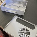
Step 5: 3D-Print


Once I was satisfied with the object, I exported 4 models as separate STL files and imported two smallest objects in Cura. Since I have already considered the support structure of the model while designing it, I didn't need to generate any support for this print (which would save a ton of time). I played with different resolution settings in Cura and decided to use a 0.16mm layer height.
Update: I printed two more of these bowls with my new wood filament.


