

Introduction: Device for Visually Impaired People

Disabilities are characterized as a type of physical, mental, intellectual or sensory impairment that can be temporary or permanent. The origin of a disability is classified as follows: birth, illness, accident, advanced age, or any other cause.
Visual disability is a condition that affects the perception of images totally or partially in people. Children with this disability from an early age may have delays in motor, linguistic, emotional, social and cognitive development. In the case of adults, it may result in lower employment rates and also contributes to social isolation.
In this project, we will develop a prototype of glasses with two infrared sensors to prevent users who suffer from myopia from colliding with obstacles.

Supplies


- 2 sensors VL53L0X
- Protoboard
- Jumpers
- Lens frame
- Filament
- Thermofit 1/8''
- Silicone Rubber
- Arduino nano
- 9V Batteries
- Switch on/of
- Buzzer
- PCB
Step 1: . Sketch

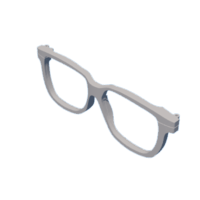
Elaborate in SolidWorks a sketch of lenses of a common model.
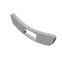
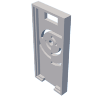
With the elaborated sketch of the lenses a base is generated where it will have holes for the passage of the connections and the base of the PCB where they will be placed in the rods of the lenses.
With the sensors that will be placed in the lenses, they will be placed in the frames on each side, then they will be send to print the sketch that will be used to place the PCB.
Step 2: Conection Diagram

The schematic shows the detailed connection of each of the sensors with the arduino nano, as well as the buzzer.
The battery is connected to a switch to limit the power flow and ideally supply the battery.
Specific conecctions:
VCC: Connect to the 5V pin of the Arduino Nano.
GND: Connect to the ground pin (GND) of the Arduino.
SDA and SCL: Connect to the I2C data pins of the Arduino (A4 and A5, respectively).
Buzzer:
Positive: Connect to a digital pin of the Arduino, such as pin 7.
Negative: Connect to a ground pin (GND) of the Arduino.
Switch:
One end connects to the battery and the other to the Arduino's VIN.
Step 3: Programming


A code is made in Arduino IDE for the programming of the sensors.
Use the VL53L0X library to initialize and read distance measurements from the sensor you need know the sensor can measure distances from 30 mm to 2 m.
Buzzer:
Configures the buzzer pin as an output.
Turns the buzzer on (by specifying HIGH on the pin) when the distance measured by the VL53L0X sensor falls below a specified threshold and the switch is on.
It turns the buzzer off (by specifying LOW on the pin) when the distance is greater than the threshold or the switch is off.
Test the code with the Arduino Nano.
Attachments

Step 4: Assembly


With a phenolic copper plate the Arduino Nano is placed to locate the connections that will have with the sensors before soldering with tin.
With the connections established we proceed to cut the phenolic plate to reduce its dimensions and to fit perfectly with the printed sketch.
Once this step is done, start soldering the wires with the respective pins of the arduino for the connection with the sensors.
Before attaching the sensors to the lenses, tighten the frames to prevent the lenses from closing and proceed to attach them.
Connect the male and female wires to the sensors. The connections are Vin, GND, SCL and SDA.
Place the wires attached to the lens rods.
With a thermoflex placed around the rods and wires, heat fit using a lighter.
Place a base for a 9-volt battery on the sketch for the PCB to secure the power supply for the arduino.
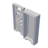
Step 5: Files
The following files are the prototype modeling files


![Tim's Mechanical Spider Leg [LU9685-20CU]](https://content.instructables.com/FFB/5R4I/LVKZ6G6R/FFB5R4ILVKZ6G6R.png?auto=webp&crop=1.2%3A1&frame=1&width=306)


