Introduction: Yet Another RC Robot Project
There are many RC robot projects out there on the internet. But I need one to meet the following needs: controlled by standard RC radio with a reasonable range (say half a mile); it must be powerful enough to run uphill on the grass (I got a big slope in the backyard), cut grass, and spread fertilizer; clean the driveway. I don't expect it to shovel snow because that would require too much power. it should be extensible to provide future functionalities with programmable microcontrollers.
The first step before building anything is to do research on what's already been built by others and to find out the options. Here is a summary of what I have found as of early 2017:
Option 1: Use Android App on cellphone or tablet to send signal to microcontroller via bluetooth. The microcontroller drives MOSFET based H-bridges. The video above shows what I built several years ago with this approach. However, this method has a number of drawbacks: the range is too short (about a few meters); the screen is hard to see outdoors; controlling the robot on the screen lacks appeals. Perhaps this approach is more appropriate for indoor applications. But no grass need to be cut indoors, and I already have a robot vacuum cleaner. Nevertheless, it works well with this approach, and the implementation is relatively straightforward. Of course, you will need to either develop an App or find one that is compatible, in addition to the hardware setup on the robot side.
A similar approach is to use WiFi instead of Bluetooth for sending signals which gives a longer range, although the implementation is a bit more complex than using the Bluetooth. However, it may worth a try given the low price of WiFi chips such as ESP8266.
Option 2: Use RC radio to send signal to the standard receiver, which then drives the H-bridge directly (or drive servos and then motors, etc). This approach works well since the hardware is dedicated to driving the robot and it runs in realtime. I have seen examples of using Sabertooth motor controllers which appears to work well, although I have not personally tested it. Aside from its cost, the main downside is that it doesn't use microcontroller so there is limited functionality and extensibility.
Option 3: Use RC radio to send signal to the standard receiver, which then passes to microcontroller for processing, and in turn drives the H-bridge. I like this approach because it has a lot of potential functionalities to be added with the microcontroller, given the popularity of Arduino, etc. Unfortunately, this approach is easier said than done, partly because you will be using a microcontroller to do too many things, including handling the signals from the receiver. Nevertheless, previous projects have shown that this is doable so I will try this method in this project.
Step 1: The Bottleneck Interfacing Radio Receiver With Microcontroller
It turns out that getting a fast and robust communication between the radio receiver and the microcontroller is not as simple as it sounds. Part of the problem is that microcontrollers are really multitasking computers, while radio receivers are typically designed for servos instead of computers. Many people have tried various methods reading receivers with microcontrollers such as Arduino with varied success (pulsein, interrupts, etc). It appears that one reliable implementation is made available by Duane at his website http://rcarduino.blogspot.com/ with his RCArduinoFastLib. At this point I was able to compile it and upload to Arduino Nano, but realized that it is taking away the PWM channels that I was going to use for driving the H-bridges.
Although his library kind of works, I don't yet fully understand how he handles things. For example, in his library there are functions for servos, which confuses me because one would think that the receiver can drive servos directly so why bother with the Arduino (perhaps handle more servos). Another issue is that he uses STEERING_OUT_PIN 9 which took away the PWM channel I plan to use. On the other hand, I changed PIN 9 to PIN 12 and so far I didn't see any problem. This confuses me as well: if PIN 12 works, why occupy PIN 9 ? Also, what does STEERING_OUT_PIN really do? It doesn't really look like it's used for output.
In any case, I am still testing the library and so far so good. I was able to get the correct values from the serial monitor although haven't tested the PWM. In the worst case if the PWM channels are not available, I will have to switch to a Mega board. So stay tuned.
After several hours of testing, I found out that RCArduinoFastLib is best used for race cars, and may not be needed for what I am trying to do, which is a slow moving robot. As a result, I decided to use a simple interrupt and pinchange method to read the receiver, and now I have all the PWM channels back for the motor controller. The Arduino Nano works fine for the project. Now I am ready to move on to the next step.
Step 2: Interfacing the Arduino Nano Microcontroller With the H-bridge
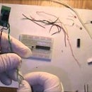
I have previously built a power H-bridge which can drive a wheel chair. It was used for my previous version of the RC robot with Android-bluetooth control. Now I need to modified the interface to connect Arduino Nano to the H-bridge. This part is relatively straight forward, except some soldering work is needed to get the pins in the right place, then use DuPont wire to connect.
For small robots, H-bridge chips are available, such as L293D. It can drive small motors but isn't powerful enough to drive a lawnmower. The powever H-bridge I built can handle about at least 250 Watts each.


