

Introduction: 3 × 3 × 3 Led Cube With Arduino

Hello guys,
Welcome to my led cube .it's easy, only thing to do is to learn code.
Even I built my cube by referring to some of the instructables website.
Step 1: Pre Requisites


First of all for this cube you need simple things
1) 27 led's (any color).
2) some single strand wires.
3)arduino uno .
4) 220 ohm resistors nine pieces.
5) 3 transistors ( 2N2222 )
6)small pcb board .
Step 2: Soldering Led's


in this step,make a mould for led's.
Take a cardboard sheet .measure length of negative leg of led and make appropriate holes and embed led's in it and bend negative legs and solder them .
Make three sets of 9 led's whose negative leggs are soldered together.
Now bend positive legs slightly and solder the three layers also. After the soldering it should look like the image shown in above picture
Step 3: Soldering Rest of Circuit
for the rest if circuit u need 9 220 ohm resistors and three 2222 transistots.
From the base layer, solder each of led to one resistor.
Next from each of layers solder them to collector of each transistor.
The base of the transistor should be connected to arduino board and the emitters of three transistors should be grounded to arduino ground pin.
Step 4: The Code
void setup()
{ pinMode(1,OUTPUT);
pinMode(2,OUTPUT);
pinMode(3,OUTPUT);
pinMode(4,OUTPUT);
pinMode(5,OUTPUT);
pinMode(6,OUTPUT);
pinMode(7,OUTPUT);
pinMode(8,OUTPUT);
pinMode(9,OUTPUT);
pinMode(10,OUTPUT);
pinMode(11,OUTPUT);
pinMode(12,OUTPUT);
} void loop()
{
for (int kat = 10; kat <= 12; kat++)
{ for(int kolon=1; kolon<=9; kolon++)
{digitalWrite(kolon,HIGH);
digitalWrite(kat,HIGH);
delay(50);
digitalWrite(kolon,LOW);
digitalWrite(kat,LOW);
delay(50); }
for (int kat = 10; kat <= 12; kat++)
{ digitalWrite(1,HIGH);
digitalWrite(kat,HIGH);
delay(100);
digitalWrite(1,LOW);
digitalWrite(kat,LOW);
delay(100);
digitalWrite(2,HIGH);
digitalWrite(kat,HIGH);
delay(100);
digitalWrite(2,LOW);
digitalWrite(kat,LOW);
delay(100);
digitalWrite(3,HIGH);
digitalWrite(kat,HIGH);
delay(100);
digitalWrite(3,LOW);
digitalWrite(kat,LOW);
delay(100);
digitalWrite(6,HIGH);
digitalWrite(kat,HIGH);
delay(100);
digitalWrite(6,LOW);
digitalWrite(kat,LOW);
delay(100);
digitalWrite(9,HIGH);
digitalWrite(kat,HIGH);
delay(100);
digitalWrite(9,LOW);
digitalWrite(kat,LOW);
delay(100);
digitalWrite(8,HIGH);
digitalWrite(kat,HIGH);
delay(100);
digitalWrite(8,LOW);
digitalWrite(kat,LOW);
delay(100); d
igitalWrite(7,HIGH);
digitalWrite(kat,HIGH);
delay(100);
digitalWrite(7,LOW);
digitalWrite(kat,LOW);
delay(100);
digitalWrite(4,HIGH);
digitalWrite(kat,HIGH);
delay(100);
gitalWrite(4,LOW);
digitalWrite(kat,LOW);
delay(100); } }
In the above code kat refers to row and kolon refers to column
Change code to get different patterns and enjoy guys.
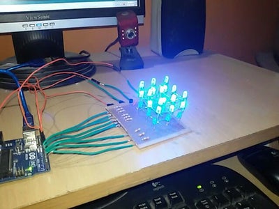
Step 5: Connecting to Arduino

1) now connect 9 wires from 220 ohm resistors to arduino digital pins (pin2 to pin 10 ).
2)Next from base of transistors connect to pins 11,12,13 respectively.
3)from emitters of transistors connect them to arduino ground.
That's all, your circuit is done and now it's ready to test.

![Tim's Mechanical Spider Leg [LU9685-20CU]](https://content.instructables.com/FFB/5R4I/LVKZ6G6R/FFB5R4ILVKZ6G6R.png?auto=webp&crop=1.2%3A1&frame=1&width=306)


