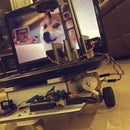
Introduction: 3D Printed Robotic Blimp - It Flies, I Guess?
As my friend Sam and I were closing up our senior year of high school, we figured we should do something fun before we went to college. That's why we decided to build a 3D printed robotic blimp that can be maneuvered either manually or through hand-gesture. In this quick tutorial, we will document our progress from the very beginning to the end result of a working model over a period of 2 weeks.
Step 1: Components + Pricing
We have included a list of the components needed in order to finish the project.
1. Foam boards/ Access to a 3D printer/ Or actually any lightweight material you can think of to make the frame for the blimp. We would suggest you get the parts 3D printed though because we have included a set of .stl files for yall already.
2. 9V batteries. Lipos might be better, but neither of us wanted to pay extra for them so 9V batteries should be sufficient to power 4 motors and the Arduino.
3. 4 6V DC motors with propellers. We got these on Ebay.
4. Arduino Mega. I have it lying around but it can be easily purchased on Amazon or Ebay.
5. HC-06 Bluetooth module. It allows Bluetooth communication between a laptop and the blimp.
6. Adafruit Motor Shield. Like the Mega, I got this from my projects from long, long ago. If you would like to check them out, they are in my Instructables profile.
7. Helium + 36 inches balloons. Sam has a car and believe it or not, we drove to Party City 3 times in 2 days to get all of the balloons filled and bring them back to school. Tough work.
8. Electric wires, on-off switch, soldering iron. Pretty self-explanatory
9. (optional) Go-pro. Sam has one lying around, and we thought it would be cool to have aerial footage so we included it.
Since we didn't receive any funding from the school for our senior project, a lot of the materials listed above are stuff lying around our house, and therefore they might not be the most weight-optimal components. Nevertheless, they got the job done pretty well, and we paid less that $100 for the entire project. The blimp didn't break during the flight, and neither did our wallets as we pursued that moment. Win-win.
Step 2: Prototyping
Again, since we didn't receive any funding, we initially decided to use foam board from Walmart to make the frame of the blimp. We would design the frame we wanted in 3D, then would eye-ball the sketch to create a foam model. The result was mediocre at best, as you can see in the pictures. The prototypes met our expectation in weight, but the fuzzy edges and the asymmetrical beams kinda threw us off.
Unsatisfied with the models, we decided to start over again. Luckily, our school has a 3D printer, one that neither of us knew about until our physics teacher brought up that idea. With the pre-existing CAD files, it's pretty easy to export them to .stl files for 3D printing, and that's what we did in the end. Shout out to Mr. Ross for the 3D printing idea though.
Step 3: 3D Printing the Components
We gave one of the faculty members the .stl files and he got the parts printed for us. You should download the .stl files, print the part2.stl, part3.slt, and the wing.stl files TWICE, while print the part1.stl ONCE. We cut the design in half so that it fits the school's 3D printer while reducing the printing time.
After we received all the 3D printed parts, we attached them with hot glue. This process should be pretty self-explanatory, as the ending result should look like CAD file we sketched from the beginning.
Step 4: Hardware
After a lengthy sanding process, as well as attaching all 6 pieces of 3D printed parts together along with 2 pieces of wings underneath, the end result should look like the first photo. We also hot glued the 4 motors on the blimp as shown in the second picture.
As for electronics, we put the shield on top of the Arduino Mega. The right vertical motor was connected to the M3 port while the left vertical motor was connected to the M4 port. The right horizontal motor was connected to the M1 port while the left horizontal motor was connected to the M2 port. Connect a 9V battery to the external power supply slot when you start using the blimp.
TROUBLESHOOTING: If a motor turns in the wrong direction after you load the program, simply switch the position of the 2 wires of the motor. For more information on the usage of the Adafruit shield, check out the tutorial I made a while ago. Link to the tutorial https://www.instructables.com/id/Adafruit-Motor-Sh...
After connecting the motors to the shield, we connected the HC-06 to the Arduino. TX of HC-06 goes to Arduino RX1, RX of HC-06 goes to TX1. VCC goes to 5V, GND goes to ground.
We then connected the switch to the 9V clip and the power adapter. Yes, I know the USB port is not optimal, and I risked frying the whole thing, but we couldn't find a DC plug to solder the clip on, and this seems to work fine. I would suggest getting a DC plug though since the incoming power supply would be regulated there.
Step 5: Arduino Sketch
We have written a short Arduino sketch that allows the Arduino board to receive data sent through Bluetooth. This also allows the board to control the motors and the blimp movements accordingly to the data it receives.
In order to use this, you have to download the Adafruit Motor shield library.
Download the library by clicking the link below. https://github.com/adafruit/Adafruit-Motor-Shield-...
Uncompress the ZIP file onto your desktop (to make it easier). Rename the uncompressed folder AFMotor. Be sure that there are the AFMotor.cpp and the AFMotor.h files in the AFMotor folder. Go to My documents on your computer. Find the arduino library folder and put the AFMotor folder inside it. Restart your Arduino IDE and check if you have a submenu called File -> Example -> AFMotor If you can see the submenu, you have successfully installed the shield's library. If you can't see the submenu, check the steps above. If you still can't see it, look for a solution online from the manufacturer or from the site below. https://learn.adafruit.com/adafruit-motor-shield/...
After that, it's pretty simple. Download the sketch and upload it on your board.
Attachments
Step 6: Processing - Manual Mode
This sketch allows users to control the blimp manually using the laptop's keyboard.
To use this, download the Processing sketch. This sketch used another external library called ControlP5, and you need to download it before running the sketch. To download the library, go to Tools, click on Add Tool. A new window will pop up, go to Libraries, and look for ControlP5. Click Download to download the library.
Remember to turn on Bluetooth on your laptop, then pair the laptop with the HC-06. The default password is 1234. If paired successfully, the HC-06 will appear with a COM port on Windows. Our COM port was COM5, so as the default COM port for this Processing sketch. If your com port is not COM5, look in the sketch and change COM5 into whatever your port is. Otherwise, you can enter your COM port in the field and hit ENTER to switch to your desired COM port.
Controlling options:
UP arrow = move forward, LEFT arrow = turn left, DOWN arrow = move backward, RIGHT arrow = turn right
'e' = upward motion, 'f' = downward motion
'w' = increase speed, 's' = decrease speed;
ESC = quit mode
Attachments
Step 7: Processing - Color-sorting Mode
This sketch allows users to control the blimp using colors.
Before running the sketch, be sure to download the ControlP5 library, turn on Bluetooth, pair the 2 devices, and select the right COM port.
What this sketch does is that it recognizes 2 default colors red and green. If users drag a small piece of bright red tape to the UP or DOWN box, the sketch will send data to control the blimp's upward or downward movement. In the same manner, if users drag a small piece of bright green tape to either the FORWARD, BACKWARD, LEFT, or RIGHT box, the sketch will send data to control the blimp to move in the respective movement.
Although the 2 tracked default colors are red and green, users can alter the color that they want to be tracked by changing the RGB threshold.
Attachments
Step 8: Why Not Let It Fly?
After uploading the code and testing to see if the model worked (it did fortunately), we finally added balloons to make this thing, well, fly. First we needed to find the blimp's center of gravity so that it would have the best stabilization. After attaching the hanger, we filled up the balloons at Party City, and then bring them back to school to attach them to the blimp. During our trip, we popped some, which explained why we had to come back to this place not once, but 3 times to get new balloons. It was very frustrating at the time, but in the end it was all worth it because..
IT WORKED!! It flew around just as we expected, but it moved rather slow even though we turned on full throttle.
It actually worked better when we presented it in public because it was not attached to a safety string as it was inside the room, though it was not as responsive to turning as we expected. We unfortunately didn't record anything during our presentation, so this is the only footage we got.
Nevertheless, this process was a fun 2 weeks, though it shouldn't take us that long to finish this project. We learned more about electronics, 3D printing, and coding, and it's also a good way to end our high school career, as well as to prepare for college as we both seek to do something science-y in the future.
-------------------------------
Thanks for checking out this Instructables. Please like, share and subscribe, and let us know if you have any question. We would love to answer them if we can. Other than that, till next time!!

Participated in the
Make It Fly! Contest 2017

Participated in the
Bluetooth Challenge


![Tim's Mechanical Spider Leg [LU9685-20CU]](https://content.instructables.com/FFB/5R4I/LVKZ6G6R/FFB5R4ILVKZ6G6R.png?auto=webp&crop=1.2%3A1&frame=1&width=306)


