

Introduction: 4x4x4 LED Cube
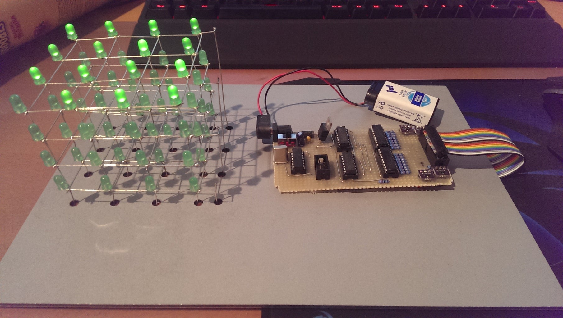


In this tutorial I will cover the build of a little 4 by 4 by 4 LED cube I built. It's being controlled by an ATTiny44 and uses ShiftRegisters for port-expansion.
I expect you to know how to solder and how to read schematics, the knowledge of ohms law, so you can calculate the resistors needed.
Step 1: Partslist
For the cube you will need to following parts:
- ATTiny44
- 2x 74HC595 (Shiftregisters)
- 2x ULN2803A (Darlington Arrays)
- 4x IRLML2244 (P-Channel Mosfets; LogicLevel; SMD!!!)
- 4x 22Ohm resistors (for mosfets, stops ringing)
- 16x resistors (calculate them yourself, for LEDs)
- A few capacitors for decoupling. 100nF are enough if you get one of those for each IC. I just have a big electrolytic 100µF cap at the end of my regulated power supply, so I don't have any more caps except the 100nF thing between GND and the datapin or so...
- PCB (perfboard, etched, etc.)
- thin wire
- ribbon wire
- jacks (for ICSP and cube)
- plugs (same here)
- programming gear (ICSP programmer etc)
- regulated 5V power supply (optional: LM7805 + capacitors)
- external Quartz + capacitors (optional, I took a 20MHz one)
Step 2: Calculating the Series Resistors for the LEDs
It's pretty straight forward to calculate those.
We have an output of ~5V from the ATTiny (no voltage drop due to CMOS technology). VCE(sat) of the darlington arrays is around 1.3 volts. Now you add the forward voltage of your LEDs and substract the sum from the 5 Volts and you have the voltage drop on your series resistors:
1.3V + 1.8V = 3.1V
UR=5V-3.1V=1.9V
To get the resistance you now need the current you want running through your LEDs (If).
R = UR/If = 1.9V/30mA = 1.9V/0.03A=63Ohm.
The LEDs I used needed a series resistor w/ ~82Ohms resistance.
Step 3: The Schematic

On the schematic, you see two big Jacks.
One has 6 pins, it's for the ICSP. The one with 20 Pins covers the 16 LED-Cathodes and 4 LED Anodes.
In the cube, each layer will have a shared Anode. Each of the 16 LEDs of one layer will have a dedicated Cathode, controlled by 1 of the 2 DarlingtonArrays controlled by ShiftRegisters (each has 8 outputs). I am using SMD mosfets. You might search for throughhole FETs OR buy some SMD to THT adapters. Remember that you need P-Channel Mosfets with LogicLevel (5V)
Step 4: Explanation


As said before, we have 4 layers à 16 LEDs. We always control 1 layer at a time. That means:
- Anode gets 5V (by MOSFETs)
- We fill the shiftregisters
- We latch the shiftregisters
- LEDs light up
- We disconnect the Anode and continue w/ the other Layers
- Repeat infinitely (until we cut the power)
Step 5: Building the Cube
To build the cube, I suggest using a piece of Wood with holes in it. You can just stick the 16 LEDs into it, it should look like a 4 by 4 Matrix. Then bend over the Anodes (long lead) and solder them together.
When you finished each layer, stack them over another and solder together all the Cathodes which are on top of each other. You can also add a few wires to support the grid.
I don't have any photos of the build process because I'm making this instructable after I finished the cube^^
Step 6: Building the PCB

If you know how to solder and how to read schematics you should be all fine. In my PCB, I also have an external quartz and a regulated power supply. I also added a gigantic diode, so i can't destroy my ATTiny accidentally.
I reccomend using a few wires on the back of the PCB because the outputs of the Shiftregisters are kinda in the opposite direction of the inputs from the darlington arrays...
The violet thingies are SMD to THT adapters I designed. I ordered them at oshpark, here's a link where you can order them: https://oshpark.com/shared_projects/I52wfkUo
You will need to add headers to it though^^
Step 7: Programming the Thing
For programming, just use an ICSP programmer.
Heres an example program I made. It activates all LEDs after another, deactives all of them indefinitely.
http://hastebin.com/aguhubetak.coffee
It's an arduino program since I programmed the Tiny w/ AtmelStudio and VisualMicro (I like the arduino libs).


