

Introduction: 555 Timer Emulator for Arduino


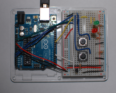
This is an emulation of a 555 timer chip that runs on an Arduino. It can run most basic 555 circuits with no change to the program or the wiring of the emulator. The picture shows the emulator setup to run an astable oscillator circuit.
The first two steps show the wiring of the emulator and the program.
The next steps show different 555 circuits running on it.
This is not really a practical way to do things. If you are serious about the 555 it is best buy a chip. You can find them for under $1.00 any place that sells electronics parts. This was an experiment to see if I could do it.
All the parts needed to complete this project are available at https://www.sparkfun.com/. They also carry a resistor kit and a capacitor kit that will give you all the values needed for this project, and more.
If you want to learn more about the 555 this online E-book shows lots of 555 circuits.
Also please check out my 555 collection of instructables at https://www.instructables.com/id/555-Timer-Circuits-1/
and my Arduino collection at https://www.instructables.com/id/Beginning-Arduino/.
Step 1: Make the Emulator


To build the emulator you will need:
- Arduino (I used an Uno.)
- Breadboard
- Assorted colors of 22 gauge hookup wire
- Red LED
- Green LED
- 2 330-560 Ohm resistors for the LEDs
- 1 K resistor to the base of the transistor
- NPN transistor (I used a 2N3904, a 2N2222 or most general purpose NPN transistors will work.)
Build the circuit as shown in the picture and the diagram.
Notice the polarity of the LEDs. The anode (long lead) of the green LED is connected to the yellow wire and the cathode is connected to ground through a resistor. The cathode of the red LED is connected to the yellow wire and the anode is connected to the positive rail through the resistor.
The top eight rows on the breadboard are the eight pins on the 555 chip:
- Ground
- Trigger - When the voltage on the trigger falls to 1/3 of VCC the output pin goes HIGH.
- Output - It is hooked up to two LEDs, the red LED lights when the pin is LOW and the green when it is HIGH.
- Reset
- Control (Not implemented)
- Threshold - When the voltage on the threshold is greater than 2/3 of VCC the output pin goes LOW.
- Discharge - When the output pin is LOW it is disconnected and when the output pin is HIGH it is connected directly to ground.
- VCC.
This circuit is just the emulator, you need to build one of the following 555 circuits before it will do anything.
This emulator has only been tested with the circuits included in this instructable. I'm sure it has some limitations.
Step 2: Upload This Code to Your Arduino
/*******************************************
 * Filename: 555-Emu.ino
 *
 * Emulates the 555 timer chip on an Arduino.
 *
 * Arduino      Emulator breadboard
 *   5V            Positive rail
 *   GND           Ground Rail
 *   A0            Row 2 - Trigger
 *   A1            Row 6 - Threshold
 *    5            Row 7 - Discharge
 *   10            Row 3 - Output
 *
 *******************************************/

/*******************************************
 * setup() function
 *******************************************/
void setup()
{
  pinMode(5, OUTPUT);
  pinMode(10, OUTPUT);

  digitalWrite(5, LOW);
  digitalWrite(10, LOW);
}

/*******************************************
 * loop() function
 *******************************************/
void loop()
{
  int discharge = 5;
  int output = 10;

  int trigger = analogRead(0);
  int threashold = analogRead(1);

  if(trigger < 338)
  {
    digitalWrite(discharge,LOW);
    digitalWrite(output, HIGH);
  }

  if(threashold > 686)
  {
    digitalWrite(discharge, HIGH);
    digitalWrite(output, LOW);
    while(analogRead(trigger)>338);
  }
}
This code will run all the 555 circuits in the following steps with no modification.
Attachments

Step 3: Emulate a 555 Astable Mode Oscillator

The most common use of a 555 chip is as an oscillator or timer.
To build the circuit you will need:
- 2 10 K resistors
- 10 uF electrolytic capacitor
- Jumper wires
You can change the frequency by changing the value of the capacitor and/or the 10 K resistors. The value of the capacitor and resistors is intended to be a starting point. Less resistance or capacitance will make it run faster, and more will make it run slower. The frequency is inversely proportionate to the RC values.
When the charge on the capacitor rises above 2/3 of VCC the output pin goes LOW and the capacitor starts tp discharge. When the charge in the capacitor drops to 1/3 of VCC the discharge pin is disconnected allowing the capacitor to charge, the output pin goes HIGH, and the cycle continues.
It will not run nearly as fast as a real 555 chip. If your RC values are too small the red light stays on and the green light blinks.
Step 4: The 555 Emulated in Mono-stable Mode


Mono-stable mode can also be called a one-shot. Pressing the switch will set the output pin to high for a period of time determined by the capacitor and the 10K resistor.
To build the mono-stable circuit you will need:
- 10 K resistor
- 2.2 K resistor
- 100 uF electrolytic capacitor
- Pushbutton switch
- Jumper wires
Again the 10 K resistor and the 100 uF capacitor are just starting points. Experiment with different values and observe the results.
Step 5: Bi-stable Operation, a Latch

In bi-stable mode the button on the bottom sets the output pin high, it stays high until the upper button button is pressed which resets the 555. There is a slight delay because the Arduino has to re-boot so it can't reset as fast as a real 555. While it is resetting the green LED will glow faintly.
To build the circuit you will need:
- 2 Pushbutton switches
- 2 22 K resistors
- Jumper wires
Step 6: A NOT Gate


All you need to build this circuit is a 10 K potentiometer and jumper wires.
The trigger and the threshold are tied together to make one input. Use the potentiometer to change the voltage. You will notice that when the voltage is low the output pin will go HIGH and when the voltage is high the output pin goes LOW.
The center third of the voltage range is a dead spot called hysteresis. You will have to turn the pot well past half way in either direction for the output pin to change. This is a useful circuit when you need a NOT gate that is not very sensitive.

Participated in the
Make It Glow! Contest

Participated in the
Arduino All The Things! Contest


