

Introduction: 7-segment Display Using Arduino Uno R3


A 7-segment display is a device that can display numerals and letters. It's made up of seven LEDs connected in parallel. Different letters/numbers can be shown by connecting pins on the display to the power source and enabling the related pins, thus turning on the corresponding LED segments. In this lesson let's learn how to display specific characters on it.
Step 1: Components
- Arduino Uno board * 1
- USB cable * 1
- 7-segment display (Common Cathode) *1
- Resistor (220Ω) * 8
- Breadboard * 1
Step 2: Principle
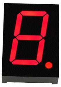
A 7-segment display is an 8-shaped component which packages 7 LEDs. Each LED is called a segment – when energized, one segment forms part of a numeral (both decimal and hexadecimal) to be displayed. An additional 8th LED is sometimes used within the same package thus allowing the indication of a decimal point (DP) when two or more 7-segment displays are connected together to display numbers greater than ten.
Each of the LEDs in the display is given a positional
segment with one of its connection pins led out from the rectangular plastic package. These LED pins are labeled from "a" through to "g" representing each individual LED. The other LED pins are connected together forming a common pin. So by forward biasing the appropriate pins of the LED segments in a particular order, some segments will brighten and others stay dim, thus showing the corresponding character on the display.
The common pin of the display generally tells its type. There are two types of pin connection: a pin of connected cathodes and one of connected anodes, indicating Common Cathode (CC) and Common Anode (CA). As the name suggests, a CC display has all the cathodes of the 7 LEDs connected when a CA display has all the anodes of the 7 segments connected.
Common Cathode 7-Segment Display
In a common cathode display, the cathodes of all the LED segments are connected to the logic "0" or ground. Then an individual segment (a-g) is energized by a "HIGH", or logic "1" signal via a current limiting resistor to forward bias the anode of the segment.
Common Anode 7-Segment
Display
In a common anode display, the anodes of all the LED segments are connected to the logic "1". Then an individual segment (a-g) is energized by a ground, logic "0" or "LOW" signal via a current limiting resistor to the cathode of the segment.
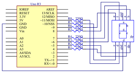
Step 3: The Schematic Diagram
Step 4: Procedures:
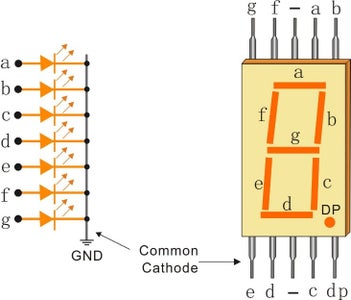


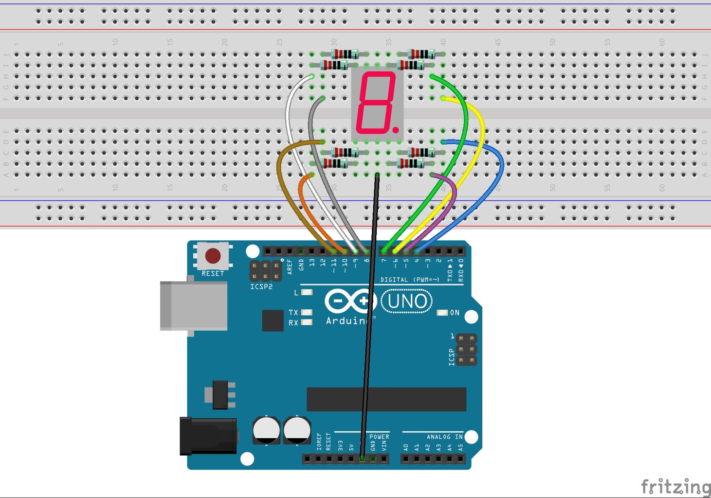
In this experiment, connect each of pin a-g of the 7-Segment Display to one 220ohm current limiting resistor respectively and then to pin 4–11. GND connects to GND. By programming, we can set one or several of pin4-11 as High level to light up the corresponding LED(s).
Step 1:
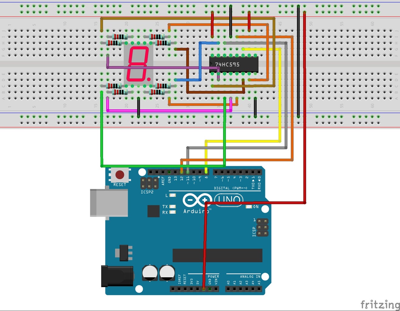
Build the circuit.
Step 2:
Download the code from https://github.com/primerobotics/Arduino
Step 3:
Upload the sketch to the Arduino Uno board
Click the Upload icon to upload the code to the control board.
If "Done uploading" appears at
the bottom of the window, it means the sketch has been successfully uploaded.
You should now see the 7-segment display from 0 to 9 and then A to F, back and forth.
Step 5: Code
//7-SegmentDisplay
//You should now see the 7-segment display cycle from 0 to F
//Email: info@primerobotics.in
//Website:www.primerobotics.in
const int a=7; //a of 7-segment attach to digital pin 7
const int b=6; //b of 7-segment attach to digital pin 6
const int c=5; //c of 7-segment attach to digital pin 5
const int d=11;//d of 7-segment attach to digital pin 11
const int e=10;//e of 7-segment attach to digital pin 10
const int f=8;//f of 7-segment attach to digital pin 8
const int g=9;//g of 7-segment attach to digital pin 9
const int dp=4;//dp of 7-segment attach to digital pin 4
void setup()
{
//loop over thisPin from 4 to 11 and set them all to output
for(int thisPin = 4;thisPin <= 11;thisPin++)
{
pinMode(thisPin,OUTPUT);
}
digitalWrite(dp,LOW);//turn the dp of the 7-segment off
}
void loop()
{
digital_1();//diaplay 1 to the 7-segment
delay(1000);//wait for a second
digital_2();//diaplay 2 to the 7-segment
delay(1000); //wait for a second
digital_3();//diaplay 3 to the 7-segment
delay(1000); //wait for a second
digital_4();//diaplay 4 to the 7-segment
delay(1000); //wait for a second
digital_5();//diaplay 5 to the 7-segment
delay(1000); //wait for a second
digital_6();//diaplay 6 to the 7-segment
delay(1000); //wait for a second
digital_7();//diaplay 7 to the 7-segment
delay(1000); //wait for a second
digital_8();//diaplay 8 to the 7-segment
delay(1000); //wait for a second
digital_9();//diaplay 8 to the 7-segment
delay(1000); //wait for a second
digital_A();//diaplay 8 to the 7-segment
delay(1000); //wait for a second
digital_b();//diaplay 8 to the 7-segment
delay(1000); //wait for a second
digital_C();//diaplay 8 to the 7-segment
delay(1000); //wait for a second
digital_d();//diaplay 8 to the 7-segment
delay(1000); //wait for a second
digital_E();//diaplay 8 to the 7-segment
delay(1000); //wait for a second
digital_F();//diaplay 8 to the 7-segment
delay(1000); //wait for a second
}
void digital_1(void) //diaplay 1 to the 7-segment
{
digitalWrite(c,HIGH);//turn the c of the 7-segment on
digitalWrite(b,HIGH);//turn the b of the 7-segment on
for(int j = 7;j <= 11;j++)//turn off the others
digitalWrite(j,LOW);
}
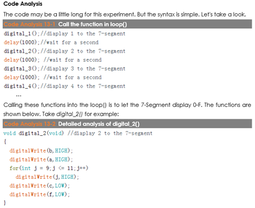
void digital_2(void) //diaplay 2 to the 7-segment
{
digitalWrite(b,HIGH);
digitalWrite(a,HIGH);
for(int j = 9;j <= 11;j++)
digitalWrite(j,HIGH);
digitalWrite(c,LOW);
digitalWrite(f,LOW);
}
void digital_3(void) //diaplay 3 to the 7-segment
{
unsigned char j;
digitalWrite(g,HIGH);
digitalWrite(d,HIGH);
for(j=5;j<=7;j++)
digitalWrite(j,HIGH);
digitalWrite(f,LOW);
digitalWrite(e,LOW);
}
void digital_4(void) //diaplay 4 to the 7-segment
{
digitalWrite(c,HIGH);
digitalWrite(b,HIGH);
digitalWrite(f,HIGH);
digitalWrite(g,HIGH);
digitalWrite(a,LOW);
digitalWrite(e,LOW);
digitalWrite(d,LOW);
}
void digital_5(void) //diaplay 5 to the 7-segment
{
unsigned char j;
for(j = 7;j <= 9;j++)
digitalWrite(j,HIGH);
digitalWrite(c,HIGH);
digitalWrite(d,HIGH);
digitalWrite(b,LOW);
digitalWrite(e,LOW);
}
void digital_6(void) //diaplay 6 to the 7-segment
{
unsigned char j;
for(j = 7;j <= 11;j++)
digitalWrite(j,HIGH);
digitalWrite(c,HIGH);
digitalWrite(b,LOW);
}
void digital_7(void) //diaplay 7 to the 7-segment
{
unsigned char j;
for(j = 5;j <= 7;j++)
digitalWrite(j,HIGH);
for(j = 8;j <= 11;j++)
digitalWrite(j,LOW);
}
void digital_8(void) //diaplay 8 to the 7-segment
{
unsigned char j;
for(j = 5;j <=11;j++)
digitalWrite(j,HIGH);
}
void digital_9(void) //diaplay 9 to the 7-segment
{
unsigned char j;
for(j = 5;j <=9;j++)
digitalWrite(j,HIGH);
digitalWrite(d,LOW);
digitalWrite(e,LOW);
}
void digital_A(void) //diaplay A to the 7-segment
{
unsigned char j;
for(j = 5;j <=10;j++)
digitalWrite(j,HIGH);
digitalWrite(d,LOW);
}
void digital_b(void) //diaplay b to the 7-segment
{
unsigned char j;
for(j = 7;j <=11;j++)
digitalWrite(j,HIGH);
digitalWrite(a,LOW);
digitalWrite(b,LOW);
}
void digital_C(void) //diaplay C to the 7-segment
{
digitalWrite(a,HIGH);
digitalWrite(b,LOW);
digitalWrite(c,LOW);
digitalWrite(d,HIGH);
digitalWrite(e,HIGH);
digitalWrite(f,HIGH);
digitalWrite(g,LOW);
}
void digital_d(void) //diaplay d to the 7-segment
{
unsigned char j;
digitalWrite(a,LOW);
digitalWrite(f,LOW);
digitalWrite(b,HIGH);
digitalWrite(c,HIGH);
digitalWrite(j,HIGH);
for(j = 9;j <=11;j++)
digitalWrite(j,HIGH);
}
void digital_E(void) //diaplay E to the 7-segment
{
unsigned char j;
digitalWrite(b,LOW);
digitalWrite(c,LOW);
for(j = 7;j <=11;j++)
digitalWrite(j,HIGH);
}
void digital_F(void) //diaplay F to the 7-segment
{
unsigned char j;
digitalWrite(b,LOW);
digitalWrite(c,LOW);
digitalWrite(d,LOW);
for(j = 7;j <=10;j++)
digitalWrite(j,HIGH);
}
Step 6: Code Analysis

![Tim's Mechanical Spider Leg [LU9685-20CU]](https://content.instructables.com/FFB/5R4I/LVKZ6G6R/FFB5R4ILVKZ6G6R.png?auto=webp&crop=1.2%3A1&frame=1&width=306)


