

Introduction: A Marking Gauge You Can't Buy


This is a project I completed several years ago. I think it would be of interest to some fellow DIY woodworkers.
I am not a professional woodworker, and having had only some years of sawdust behind me, I can at best describe myself as a serious amateur. I can’t justify and I don’t want to spend a fortune buying all the tools and equipment for the hobby, so I try to make my tools whenever I can.
I have always been using pencil and ruler, or sometimes try square and marking knife to set out my work material. This is fine most of the time, but the problems of inconsistencies in repetitive marking, misreading the ruler scale, or inadvertently shifting the ruler or try square midway soon convinced me that I needed a marking gauge.
I went to the neighborhood hardware store and bought one. It is inexpensive, made of beech with a plastic screw and a hardened iron pin, with graduations pressed on one side of the beam and the wood is not even finished. It does the job alright but I am not really happy with it.
Firstly, I do not find the scale reliable and it is tedious to set up accurately. To do so you have to take an ruler against the stylus and the stock, unscrew the beam and slide it to position, then while holding the ruler, stock and beam with one hand, you tighten the screw to lock the gauge with the other. Alternately you have to make a trial line on a piece of scrap, measure the distance and adjust the fence by trial and error. Unfortunately, the twisting motion of the screw tends to move the beam off position.
Secondly, you can’t see where you are actually marking, so if you want to start and stop marking somewhere in the middle of a work piece, you will have to peek under the beam while pulling or pushing the gauge.
Thirdly, the iron pin tends to tear the wood across the grain, or wander along with it. Filing the pin flat on one side offers some improvement however. But then I thought it would be nice to be able to use a pencil sometimes.
Finally and most importantly, I don’t like giving myself the excuse “You can’t do a nice job because you have a cheap tool!”
So I returned it and shopped around for a better one. I was shocked by what I had to pay for a more decent one. And then even deluxe models don’t seem to meet all my expectations. So I decided to make my own.
Having spent two weekends and a small fraction of what I might otherwise have to pay, I am pleased to have an excellent tool which is aesthetically pleasing to look at, and which of course I am really proud to show off.
Step 1: Design and Materials


A marking gauge is a simple contraption usually made of wood consisting of a body or fence, a beam sliding in a hole in the fence and mounted with a marking device such as a knife, stylus or pencil, and a means of locking the beam to the fence at any place along its length.
I want it to be simple and inexpensive to make, accurate, versatile, easy to set and see, and nice to look at.
After consulting a number of books, magazine articles, the web and examining a variety of commercial items in the tool stores, I settled on a traditional “grasshopper” design. My device’s apparent similarity ends with appearance only.
The fence is made of hardwood just over 2” square and about 1” thick. This is a good size for holding and gives good enough support when slid along the edge of a work piece. The top and the base have rounded profiles to make it comfortable to hold and nice to look at. The actual dimensions are not critical and you can vary them to suit your preference, the size of your hand or the material available.
Like most commercial models, two strips of brass ¼” wide and 1/16” thick are inlaid on to each face of the fence parallel to its sides and sanded flush with the wood to minimize wear of the face through frequent rubbing against rough wood during use.
The beam is also made of hardwood, about ¾” x 7/8” in cross section and about 9½” long. This length is chosen so that up to 8” of marking distance can be set up, although it is unlikely that you will ever mark anything wider than 3” to 4”. It also has rounded top and bottom edges to match the fence. The rounded profiles give the finished instrument a professional look and makes it easier to lock with a cross wedge.
I want to be able to set up the instrument easily, quickly and accurately. To do this, a precision steel rule is inlaid into one side of the beam, measuring from the tip of the marking devise. Which side to inlay will depend on your preference. It would be nice to have a ruler which runs the full length of the beam. Unfortunately, I cannot find one which is narrow enough to be inlaid nicely. The best compromise I can get is General Model No. 301 Stainless Steel Precision Rule which is ¼” wide and 6” long. Since I most likely won’t be marking anything wider than 6” any way, I consider that this is good enough.
To lock the beam I first considered using a screw like all commercial models but I soon gave up the idea. To install one I’ll need to inset a matching nut accurately in the fence to hold it. And a metallic screw marks the beam even though the latter may be protected with an inlaid brass strip (as in some commercial models). A plastic one looks cheap and is difficult to come by. Moreover, the twisting motion of a screw frequently moves the beam slightly out of position when tightened.
I therefore opt for a hidden wedge design. It is essentially a small diameter dowel (I chose ½” which is easier to make), inserted into a through hole in the side of the fence with a short length protruding from each side. A wedge cut in the middle section of the dowel engages the bottom edge of the beam. Tapping one end of the dowel jams the beam tight and tapping the other end loosens it. This locking pin is made out of a small piece of light colored hardwood. To make it interesting I gave the two ends contrasting colors by gluing a piece of darker color wood (say rosewood) onto one end. The overall length of the pin is about 2½”.
The primary marking device is a steel cutting knife (see below for actual dimensions). It is ground to a 120º spear point, flat on one side and beveled 25º on the other. I cannot buy such a knife so I made one.
The knife can be mounted like most commercial models in a hole somewhere close to one end of the beam and held in place with a screw or wedge. I don’t like this idea because the tip of the knife will then be hidden from view and you can’t see where you are marking. Carving out a small tapered hole for the knife and wedge is also not a trivial task. Moreover, a wedge tends to move the knife further into the hole as it is tapped tight, extending the tip further than intended.
Instead, the knife is mounted snugly in a vertical slot cut into the end face of the beam and held in place with #6 winged bolt (made from a #6 winged nut and a matching bolt cut from a screw) and washers. It will be clearly visible and easy to change. Also it can be simply retracted when not in use, avoiding a potential source of danger because of an exposed blade. The flat side of the knife is mounted outward. The flat surface makes a clean vertical cut while the beveled side crushes the wood fibers at an angle. Since most of the time the side marked out is where a tenon or a rabbet is eventually cut and goes to waste, the resulting edge is always square and clean.
Mounting the knife with its flat surface outward is good for marking tenons and rabbets. What about mortises? The waste goes to the wrong side along an edge. To overcome this, you can reverse the knife so that the flat side faces inwards. Unfortunately this creates two problems.
The first problem is that the zero point of the inlaid rule will no longer be correct because the cutting edge is now closer to the fence by the knife’s thickness. To correct this I cut the slot twice as deep and made a wooden shim with the same thickness as the knife. When the knife is mounted normally, the shim is placed on the outside as padding to hold it in place, and when it is reversed, the shim is placed in the inside (i.e. in the slot first) to shift the knife’s cutting edge back to the zero point.
The second problem has to do with the lateral force acting on the knife when it cuts along the wood.
When the knife cuts through wood, the crushed wood fibers give the bevel a small sideward thrust which tends to pull the fence tighter against the edge of the work. This keeps the knife from wandering and the resulting line is straight. However, if you make a very light cut, or if the instrument is used along the grain, the blade may not bite into the wood sufficiently for this to take effect. And this problem is made worse when the knife is turned around. The bevel will be on the wrong side, and the resulting sideward thrust on the blade will tend to push the fence away from the edge of the work piece.
To overcome this, I have an inspiration from the Japanese kebiki. While the knife is mounted perpendicularly, its cutting edge is swiveled at a small angle away from parallel to the fence along the direction of the stroke. I find empirically that 3º are about right and swiveling the knife at this small angle has little effect on the shape of the cut line. I am right handed and I use the pull stroke so I cut the end of the beam at 87º (viewed from the top with the fence on the right hand side). If you are left handed but use the push stroke, this configuration will be fine. However, if you are left handed and use the pull stroke, or right handed but use the push stroke, you will have to cut the mirror image or 93º.
I want to sometimes mark with a pencil. A cutting knife makes a superior marking line which is very thin and accurate and cuts the wood fibers cleanly when used across the grain. However, it is not suitable always, such as setting up dimensions when you want to be able to remove the lines easily afterwards, or along the grain on some woods where the thin cut may be hardly visible. On such occasions a pencil is a better choice.
Originally I designed one end of the beam to hold a knife and the other an ordinary pencil. I find that this is not very elegant. Then it occurs to me that, because I have to make the knife anyway, if the knife has the same cross section as a piece of carpenter’s replacement pencil lead, I can mount either the knife or the pencil in the same holder! Carpenter’s pencil lead is 3/16” x 3/32” in cross section. So I make the knife the same and cut the mounting slot accordingly.
The gauge uses either a knife or a pencil at any time. Wouldn’t it be nice to have somewhere to stow away the spare marking device and not to have to look for it when you need it? So I drill a capsule into the free end of the beam. This normally holds the pencil which is less frequently used.
This capsule is a stepped concentric hole ½” diameter 5/8” deep at the opening and ¼” diameter 2½” deep further in. The wider opening accepts a wooden cap which is a plug fitted on its side with a small peg, 3/32” thick, 3/16” wide and 3/8” long. The peg engages into an L shaped slot cut into the side of the beam. When the peg is turned clockwise it locks the cap in place. I used rosewood for both the plug and peg to give a nice accent.
Materials
for the Fence
Piece of hardwood approximately 2 1/8” x 2½”, 1 1/8” thick
Brass strip, ¼” wide, 1/16” to 1/8” thick, 1’ length
for the Beam and Knife Holder
Piece of hardwood ¾” x 7/8” cross section, 10” long
General Model No. 301 Stainless Steel Precision Rule SAE ¼” x 6”
#6 T-nut (better no prongs)
#6 stainless steel screw, ¾” long
#6 winged nut
#6 steel washer
#6 nylon washer
Small strip of hardwood ½” x 3/16” x 1½” (for the shim)
for the Pencil Capsule
Small piece of hardwood plug or dowel, ½” diameter x 5/8” long
Small strip of hardwood 3/32” x 3/16” x 5/8”
for the Locking Pin
Small piece of hardwood ½” square section, 2” long
Small piece of hardwood contrasting color, (say rosewood) ½” square section, ¾” long
for the Marking device
Old ¼” diameter twist drill (either high speed steel or carbon steel)
Carpenter’s pencil replacement lead
for the routing template
Piece of scrap hardboard or plexiglass, about 6” x 6”, 3/16” to ¼” thick
for construction
Pieces of scrap wood and dowels (see text)
Two part epoxy resin adhesive
Some carpet tape
The fence, beam and locking pin are made of hardwood. Any dense hardwood with a straight grain, good wear resistance and good dimensional stability will do. You can use different species for the different parts. You can choose for example mahogany, walnut, beech, maple or cherry, or if you fancy, an exotic wood like rosewood, cocobolo, padauk, ebony etc. Some exotics are expensive and difficult to work. I use flowering dogwood throughout simply because I happen to have a suitable piece at hand which cost me next to nothing in the first place. Dogwood is not a usual woodworking timber. However it is dense, stable, has a fine and closed grain and easy to work, and the finished product is very nice to look at.
All the other materials are common and inexpensive. Probably you can find most of them in your junk box. If not you can pick them up in any hardware store. The only exception is perhaps the ¼” wide General Model No. 301 stainless steel rule which may not be sold in any store. In any case, if you cannot find it, you may be able to substitute it with a ½” wide one although it may look a bit out of proportion when inlaid into the narrow beam.
The cost of materials (other than wood) is only a few dollars.
Tools and Equipment
You don’t need any specialized tools and you don’t have to be exceptionally skilled to work this project.
You will need most of the following basic tools:
backsaw
coping saw
hacksaw
smooth or block plane
set of chisels
electric drill
oil or water polishing stones
sandpaper of various grit sizes
various flat, half round and square files
various needle files
wooden and C-clamps
straight rule
try square
protractor
calipers
work bench
It will be exceedingly useful if you have access to some power tools. They speed things up and help get a professional looking result. You can of course do without them but then you’ve got to work a lot harder.
drill press
rotary tool
plunge router and router table
table saw and/or a band saw
For the purpose of this project I assume that you have access to and are familiar with the use of these power tools.
Step 2: Getting Started
This project took me two weekends. Most of the time however was spent waiting for epoxy resin to cure.
Spend your first weekend to plan and prepare the project. Based on the illustrations here, prepare full size drawings for the parts. If you decide to make the gauge larger or smaller, modify the dimensions accordingly. Gather all the materials. Get ready all the tools needed. Finally, prepare a checklist of the working steps (see below).
The marking gauge is made in several stages with a number of steps. Follow these carefully as it is not always advisable to work out of sequence. Although some steps may appear complicated, each step is not difficult. Since the finished product can serve you a life time, it is worth while to spend just a little more time and effort on each step.
Stage 1 Making the routing template
Stage 2 Preparing the wood
Stage 3 Making the fence
Drilling hole for the locking pin
Routing hole for the beam
Routing edge profiles
Inlaying brass rubbing strips
Stage 4 Making the knife
Stage 5 Making the beam
Fitting
Cutting the knife mounting slot
Inlaying the precision rule
Making the pencil capsule
Stage 6 Making the locking pin
Stage 7 Calibration and Finishing
Step 3: Construction: Stage 1 – Making the Routing Template

Unless you want to do it with coping saw, drills and files, you’ll need a template to rout the hole and profile of the fence.
Get a scrap piece of hardboard or plexiglass 3/16” to ¼” thick measuring about 6” by 6”. Exact size is not important as long as it offers a sufficiently wide surface for the router base to ride on.
Using the plan illustrated, cut the template board:
In the middle of the board, drill saw and file a template hole for the beam holder. Taking into account the thickness of the wall of the pattern routing guide, which for a ¼” bit in my case has a wall thickness of 1/32”, this hole has to be 1/16” larger all round.
On one edge of the board, saw and file a 6” diameter arc 2 1/8” wide (or your preferred width) as a guide for the fence’s curved lower edge. This is cut to actual size because an edge following bit will be used.
On then other edge of the board, saw and file a 2 1/8” wide (or your preferred width) curve with 1” diameter quadrants at each end as a guide for the top of the block. Again actual size is used.
Step 4: Construction: Stage 2 – Preparing the Wood

Select a piece of good quality hardwood and saw it to 2 3/8” by 2”, 1 1/8” thick. This will be used to make the fence. It is advisable to cut it slightly bigger and later be trimmed to size. Plane the faces parallel to one another, and square all the corners. This is important so that the holes which you are going to rout or drill will be square and aligned properly.
Select another piece of good quality hardwood with straight grain and no knots. Cut slightly larger than ¾” by 7/8” in cross section, about 10” long. This will be made into the beam.
Select two pieces of hardwood ½” square in cross section. One piece is lighter color (I used dogwood) measuring about 2” to 2½” long. Get another piece with a darker color for contrast (I used rosewood) measuring about ¾” long. Square off one end of each of the two pieces and glue them together end-to-end with two part epoxy resin. Do not try to use white or yellow carpenter’s glue. This kind of glue does not bind well on end grain and the joint with such a small cross section will snap as soon as there is any stress on it. Clamp the glued pieces lightly between the front vise jaws and allow the epoxy to cure for at least 24 hours. This joined piece will be made into the locking pin. If you want to avoid joining two species of wood together, you can use one longer piece and dye one end with a different color. However the result will not be as elegant.
Make a 1½” strip of hardwood ½” wide and 3/32” thick. This will be used for the knife mounting shim.
Cut a piece of hardwood plug (or short dowel) ½” diameter, 5/8” long and another hardwood strip ½” x 3/32” x ¾”. These two pieces will be used to make the locking cap of the capsule.
Step 5: Construction: Stage 3 – Making the Fence


The fence is the body of the marking gauge. It has a large hole in the middle (the beam holder) to accept a beam on which a knife or pencil is mounted. The beam is locked in place with a two way hidden wedge. The wooden face of the fence is protected with inlaid brass strips from excessive wear from constant rubbing against the edges of rough wood material. The brass strips also add a professional look to the instrument.
Drilling Hole for the Locking Pin
The locking pin is inserted in a hole drilled across the fence block from one edge to the other, halfway from each face, with its center line about 1/8” lower than the lower edge of the beam holder.
This hole should be drilled first so that when the beam holding hole is routed, the intersection of the two holes will be cleanly cut by the router.
Mark the drilling center on both the left and right edges of the wooden block. The block is just over 2” wide. To drill the hole cleanly you should use a forstner bit. A twist drill tends to leave a rather untidy entry and exit. A brad point is better. With a ½” brad point or twist drill bit you can bore the hole through in one pass but you’ll have to make sure that the drill bit is absolutely square to the block so that the hole comes through at the right spot on the other side. If you use a forstner bit, it will not be long enough. Either way you probably need to drill it from both ends. But the through hole has to line up perfectly from both directions otherwise it will be crooked and the locking pin will get stuck in the middle. To drill it perfectly follow this method:
Drilling a hole from both ends
With one face towards you, first mark the work piece faces “T” for top, “R” for right, “L” for left, “B” for base. These markings help orientate the work piece when it is drilled.
Get a piece of scrap wood with parallel faces at least 1” thick and clamp it onto the drill press table. Make sure that the table is square to the chuck. Secure a ½” drill bit (preferably a forstner or brad point but a twist drill will do) in the chuck. Lower the table sufficiently for the work piece to be put under the chuck and then lock it. Remove the work piece. Lower the chuck all the way to drill a ¾” deep hole in the backing board. Do not loosen the board or move the table. Clamp the work piece properly centered onto the backing board using a wooden clamp and C-clamps (see illustration) with the “T” edge facing right on the table, and “R” edge turned up on top. Drill the work piece to just over half its depth. Unclamp the work piece. Now insert a short (say 1½”) ½” diameter dowel halfway into the newly drilled hole, turn the work piece over and insert the other end of the dowel into the hole drilled in the backing board.
Clamp the work piece securely onto the table again. “L” edge is now facing up. However, this time make sure that “T” edge is facing left. You do this so that even if the drill press table is not absolutely square, or the work piece edges are not exactly parallel, any misalignment will cancel out and the holes will always line up perfectly. Now drill the hole through.
Routing the Hole for the Beam
Pencil diagonal lines on the face of the work piece to locate its central point. Trace and mark out the hole for the beam onto the face, centering it in position. Stick two pieces of carpet tape onto the face, avoiding the marked out area. Now carefully align the template with the beam holder hole precisely over the marked out area and stick it onto the carpet tapes.
Clamp the work piece securely in the front vise of your workbench, allowing the template to sit squarely on top of the vise jaws. With the plunge router set up with a brass template guide and a ¼” straight or spiral bit, rout the beam holder hole in three to four passes, increasing the plunge depth by about quarter of an inch at a time.
Unclamp and remove the work piece from the routing template. Cleanup the carpet tapes. Remove the template guide and router bit.
Routing the Top and Bottom Edges
The top and bottom edges are rounded for practical and aesthetic reasons. Rounded top corners make the gauge comfortable to hold in the hand, and the large radius curved bottom gives it a nice professional look.
Trace the top and bottom edge profiles onto the work piece.
Attach the routing template onto the work piece with carpet tape aligning with the top edge profile. Clamp the work piece in the end vise. To avoid splitting the grain at the trailing edge clamp a small piece of wood between the vise jaw and the trailing side of the work piece. With the router riding on top of the template and using an edge-following ½” diameter template bit, rout the top edge. If you cannot manage to rout the whole depth because the bit is not long enough, change to a flush trimming bit and trim flush the remaining depth from the back.
Now rout the bottom profile in a similar manner.
Inlaying Brass Rubbing Strips
Two strips of brass ¼” wide are inlaid onto each face of the stock so that the wooden faces are not so easily worn away from frequent rubbing with unfinished wood when the marking gauge is used.
It is unlikely that you will wear away much brass in a life time of use, so the strips need not be very thick. 1/16” is good enough, inexpensive and convenient to work with. When the strips are worn in time, they can be sanded down with the face to make it flat again.
Cut 4 pieces of brass 2½” long each.
With a ¼” diameter straight bit in the router mounted on the router table, set the routing depth a little shy of
1/16”. Set the fence ½” from the edge of the bit. Rout a trial slot on a piece of scrap first and try insert a brass strip. Adjust the routing depth until the strip is just proud of the wood face by say less than the thickness of a piece of paper. Then rout two shallow grooves running top to bottom on each face of the block along each edge. Dry fit the strips in the grooves. Make sure that they mate snugly.
Now that you have a good fit, mix some two part epoxy resin and apply thin films in the grooves and on the underside of the brass strips. It is a good idea to file a few shallow niches on the underside of the brass strips first to give the epoxy some foothold. Insert the strips into the grooves. Their ends should stick out a little from the top and bottom edges of the stock. Clamp the assembly lightly between the wooden jaws of your front vise to press fit. Some epoxy will ooze out between the wood and the brass. Clean up with a cloth soaked with a little acetone or mineral spirits. Allow the epoxy to cure overnight.
After the epoxy is properly cured trim off the brass ends with a fine hacksaw or with the rotary tool. File the ends flush with the top and bottom edges of the fence.
You now need to polish the brass strips flush with the wood. Stick a piece of 80 grit sandpaper onto your workbench or a flat surface. Holding the fence in your hand and placing it face down onto the sandpaper sand down the brass until the metal and the wood appear and feel to be one smooth surface. Rotate the work piece frequently to avoid sanding the surface on one side more than the other. Change to 180/200 and then 400 grit sandpaper and re-sand until the brass achieves a mirror finish. Do this on both faces. It is likely that after sanding some fine brass filings will get embedded in the wood and discolor it. You can remove the brass filings by rubbing with superfine steel wool, using some furniture oil as lubricant. Don’t use the steel wool dry.
Sand the top and bottom edges of the wooden block with progressively finer sandpaper for a smooth feel.
The fence is now completed.
Step 6: Construction: Stage 4 – Making the Knife


The marking gauge is fitted with a steel marking knife. The tip is cut into a V shape point with leading and trailing cutting edges. One side of the knife is ground flat, and the other is beveled at about 25º (see illustration).
The knife is normally mounted on the beam with the flat side facing away from the fence. Say if you are right handed and you mark a line on a work piece, it cuts the wood fibers on its left or flat side and crushes them on the right or beveled side. If you are marking for a dado or a tenon, the crushed side goes to waste, so you get a sharp clean edge on the good side.
On the other hand, if you are marking the right edge of a mortise, the waste goes to the left. In this case you reverse the knife so that its flat side faces the block, again leaving a clean edge on the good side.
The knife is 3/16” wide and 3/32” thick, its cross section matching that of a carpenter’s replacement pencil lead, and about 1” to 1½” long. You cannot buy such a knife so you have to make it yourself. You can easily make a knife from a piece of hacksaw or jigsaw blade, but it will be not be thick enough. I use the shank of an old twist drill. The metal is carbon steel. 7/32” diameter is perfect, but a common ¼” diameter bit is just as good. Or you can use an old ¼” chisel which you no longer use because you have upgraded to a better set of chisels, and which you just don’t feel like throwing away.
It is difficult to hold a twist drill when you try to grind it, and more so if you try to grind the shank. So mount the drill into the end of a ¾” square section wooden dowel several inches long. Drill a slightly smaller diameter hole into the end of the wood. Insert the twist drill point first into the hole and tap it in tightly with a hammer.
Holding the drill bit in its wooden holder, grind the shank on your grinder (or in my case a grinding wheel chucked into the drill press) until it has a rectangular cross section with nearly the desired width and thickness. Do not overheat the steel. Allow time between grinding strokes and make sure it is cool to touch at all times. Check the dimensions of the steel blank with calipers frequently. When they come close, grind the blank on an oilstone or water stone to final size by hand.
Now grind a 120º spear point at the end of the steel blank. The angle does not have to be exact, but the two edges of the V point should be symmetrical. Then grind a 25º bevel along both edges on one side of the blank only, leaving the other side flat. Grind slowly and take particular care because the thinner metal close to the point and bevel edge can overheat and burn very quickly. Only make short grinding strokes for a second or two at a time and allow the metal to cool down in between, preferably by dipping in a tray of cold water. If ever the steel turns blue it is already ruined. Even a slight golden discoloration indicates that it is already overheated. Should that occur, grind off the discolored area and start afresh.
After grinding to shape, sharpen and hone it in the same manner as you would sharpen a chisel. Use oil or water stones, or progressively finer grits of sandpaper to polish the blank until the flat side and the bevels take on a mirror finish. Hone down slightly the ridge where the bevels meet. This will round off the pointed tip for a smoother cut. Don’t hone a secondary or micro bevel as it is not needed.
Finally sever the knife (the shank) off from the rest of the drill bit with a cutting wheel on the rotary tool. Test for sharpness by trying the knife on a piece of paper or scrap wood. The knife is now ready.
Step 7: Construction: Stage 5 – Making the Beam


The beam slides in and out of its hole in the fence.
It has a knife mounting slot, an inlaid precision rule and a pencil capsule.
Smooth Fitting to Hole
The beam is ¾” wide and 7/8” tall in cross section. The top corners are rounded and the base is curved. The height is made slightly taller to compensate for the optical illusion that the beam is flatter than it is because of the rounding of the top and bottom corners.
Firstly plane one or both sides of the beam until it is just narrow enough for the fence hole.
With a ½” diameter rounding bit in the router mounted on the router table, rout the top curved corners. It is advisable to do a dry run on a piece of scrap wood to make sure that the curve and rout depth are correct.
Trace the bottom curve profile onto the ends of the beam, and run two pencil lines to mark the new edges on each side. Using a smooth plane or block plane, plane off the excess wood little by little, try fitting the beam into its hole at each step. Don’t try to plane to exact size in one go. If you do, you will inevitably end up with an undersized beam.
When you find that the beam may just slide in tightly, stop planing and lightly sand and scrape the base and corners until you can smoothly slide it throughout its length.
Cutting the Beam Face for Knife Mounting Slot
The knife is mounted in a slot at one end of the beam and held in place with screw and washer.
I have already explained under “The Design” that to keep the knife from wandering away from its intended line, it is purposely mounted off parallel with the fence at a small angle of 3º.
I am right handed and I prefer to use the gauge on the pull stroke. So if you look down at the marking gauge from the top, the cutting knife is mounted at 87º instead of 90º from the axis of the beam. If you are left handed and use the push stroke, you can use the same configuration. But if you are right handed and use the push stroke, or left handed and use the pull stroke, you will have to mount the knife at 93º instead.
Use a fine backsaw or the band saw to make a 87º cut across the end of the beam, removing about ¼” of material. The longer side is the leading side in the direction of the stroke. Clean up the saw marks with a chisel or sandpaper.
Installing the Knife mounting T-nut
Make a center mark on the beam’s end face 3/8” from the side and ½” from the top edge. Loosen the drill press table and lower it so that it is about 4” below the chuck. Swivel it off to one side. Clamp the beam end face up between the jaws of a wooden clamp, with about ½” sticking above the clamp. Chuck a 5/8” diameter forstner bit in the drill press. Position the wooden clamp so that the forstner bit is directly over the drilling mark. Secure the wooden clamp onto the table with C-clamps and tighten the table. Switch on the drill press and lower the chuck until the forstner bit just bites into the wood. If the bit marks a full circle it is square with the beam’s end face. If not, loosen the wooden clamp slightly and shift the beam’s vertical alignment. Once the bit is square, drill a 1/16” deep flat bottom dish onto the end face. Without moving the table or unclamping the work piece, change to a 3/16” diameter brad point bit and drill a ¾” deep hole into the center of this dish.
Use a hacksaw to cut off one side off the flange of a #6 T-nut right against the threaded cylinder. File clean the sawn edge and flatten the prongs. Using a triangular needle file cut a few notches into the side of the threaded cylinder. These notches help keep the nut secured in place after being glued in. Place the T-nut into the hole and dish, with its cut edge parallel to the beam’s flat sides. Mix some two part epoxy resin and apply it to the underside and the threaded cylinder of the T-nut. Make sure that no resin gets into the threads or in the end of the long hole where it might later cause obstruction. Then fill the dish with epoxy, avoiding the threaded hole, and spread epoxy over the rest of the beam’s end face. When the epoxy starts to cure, it will become more runny and soaks into the end grain strengthening it after the resin hardens. Leave the epoxy to cure overnight.
Cutting the Knife mounting Slot
When the resin has hardened, file off any excess if necessary. Clamp the beam vertically in the front vise, and using a protractor to check that its length is inclined at 87º rather than perpendicular, thus aligning its face parallel to the bench top. With a try square placed upright on top of the vise jaw as a guide, use a thin saw blade (a trimming saw or a coping saw) to cut two kerfs defining a 3/16” wide slot, just short of 3/16” deep into the end face. One kerf should be cut right against the cutout edge of the T-nut flange. Remove the waste between the kerfs with a very narrow chisel or a section of hacksaw blade. Square off the cutout with needle files, making it exactly 3/16” wide, and about a thin paper’s thickness short of 3/16” deep. Make sure that the groove’s sides are square to the beam end face (hence 3º off parallel with the beam’s side), and its bottom flat. If the bottom is convex the knife will not fit well, and if it is concave, the pencil will snap under the washer. Try fit your knife into the slot and trim the width of the slot for a snug fit. Leave the knife in the slot.
Making Knife mounting Shim
Now take a small piece of hardwood measuring ½” x 3/32” x 1½”. Cut it into a L-shape so that its longer leg is 3/16” wide and 7/8” long, and its shorter leg is ½” wide and just as long.
Without removing the knife, put the shim on top with its short leg hooking onto the top of the beam, preventing it from sliding away before it is secured in place. The shim should be just proud of the end face of the beam. This allows the washer to have some holding surface.
Put a ½” diameter steel washer over the T-nut, and a nylon washer on top. Cut off the head from a ¾” #6 screw and twist the bolt into a #6 winged nut, securing it permanently with a drop of crazy glue in the thread. Lightly tighten the washers with this winged bolt. The knife should be held securely. Alternately you can simply use a #6 screw but the modified winged bolt makes it simpler to change the knife.
Loosen the winged bolt and take out the knife and shim. Insert a piece of carpenter’s pencil lead into the slot and replace the shim. It should fit too. Tighten the bolt to make sure that it is held securely without snapping.
The shim will protrude from the bottom of the beam slightly. Trim this off with a file and sandpaper.
You will notice that the mounting slot is offset from the center line of the beam face in the direction of travel. This is done on purpose so that you can easily see the knife’s tip when you move the instrument across the wood, and this offsetting has no adverse effect on use.
Inlaying the Steel Rule
The General Model No. 301 steel rule comes with a sliding pocket clip. This is not used.
Putting a ¼” straight bit into the router mounted onto the router table, set the depth to just a little over the thickness of the steel rule so that there is some room for the adhesive. Rout a shallow groove onto a piece of scrap wood to try first. Adjust the cutting depth until the depth is right.
With the knife mounted in its slot bevel outwards and with the shim on the outside, mark the position of the point on that side of the beam which is more convenient to you. Mark the other end of the rule 6” away. Clamp stops onto the router table to limit the start and end travel so that a 6” groove (edge to edge, not center to center of the bit) can be routed in the beam between these two marks. With a featherboard holding the beam against the fence, rout the groove in the beam, taking care to drop the wood onto the bit to start the run, and stop the motor before removing it.
Square off the two ends of the groove with a ¼” chisel. Try insert the steel rule into the groove and make sure that the two ends fit. DO NOT attach the steel rule to the beam at this stage until you have calibrated the gauge (see below).
Drilling the Pencil Capsule
The capsule consists of two concentric holes drilled into the free end of the beam. The wider hole accepts the cap and the narrower hole stores the pencil. This storage is capped by a wooden plug with a peg which engages and locks in an L shaped slot cut into the side of the beam.
First, mark the center point of the end face of the beam. Clamp the beam end face up under the drill press chuck, in the same manner as described above in “Knife Mounting Slot”. Using a ½” diameter forstner bit bore a 5/8” deep hole at the center mark. Then, if you are brave you can change to a ¼” diameter brad point or twist drill and bore a 2½” deep hole, measured from the bottom of the wider hole. This can be tricky because of the end grain and depth. The beam may not be held that squarely under the chuck and the hole would not be straight, coming out of center at its bottom. Since this hole is hidden, it may not matter, but any imperfection bothers me. Would it bother you too?
Instead, make a simple drilling jig which is a small block of hardwood 1” x 6” x 1”, square on its faces and sides, with a ¼” guide hole drilled perpendicularly through one of its faces centered 3/8” from a long edge. This block is clamped over the edge of the workbench, with the guide hole close to the edge and facing you. With the help of a try square, place the beam flat face down with its end face dead against the back of the guide hole block. Insert a ¼” brad point drill into the guide hole to locate the center of the hole made by the forstner bit in the beam face and adjust the beam into correct position. Clamp the beam onto the table. Chuck the brad point bit on your portable electric drill and bore the deep hole through the guide hole. You bet it will be straight and centered! It is more helpful if you have a ¼” steel drilling guide insert (which I actually used) but because this jig is only used once for a single hole, the hardwood guide hole is good enough.
Making the End Cap
The capsule is capped with a wooden plug ½” diameter and 5/8” tall. You can make this from a ½” hardwood dowel. However, to give it accent I cut a ½” plug from a piece of rosewood from the end grain. But there is a small problem, the cutter does not cut deeper than ½” and the plug comes out tapered.
Well, I applied the cutter to its maximum depth and then cut off the stock 1/8” further down. The waste is then pared away and the extended end rounded off with sandpaper. Stick a small piece of 220 grit sandpaper around one end of a short piece of 3/8” dowel and use this make-shift “file” to trim the top part of the cap cavity large enough to accept most of the plug with only about 1/8” remaining. The taper turns out to be a blessing in disguise. Because of it the bottom end of the cap hole will not need to be widened.
A small wooden peg is fitted onto the side of the plug. This peg is 3/32” thick, 3/16” wide and 3/8” long. There are several ways of attaching this peg. Although I used a different method, the simplest way is as follows: Cut the peg to its width and thickness, but 5/8” long. Drill a 3/8” hole ¼” deep on the side of the plug, centered ¼” from the narrower end. Insert the peg into the hole with its narrow edge aligned with the plug’s length and secure it in place with small pieces of shims on both sides. Some wood glue applied to the shims before insertion permanently fixes the peg. File off excess wood from the shims and sand smooth the surface.
Next cut the slot into the side of the beam. The slot is shaped like an inverted L. The horizontal cutout accepts the peg as the plug is put into the cap hole, and the vertical one engages and disengages the peg as the cap is rotated.
Mark out an L shaped area on the right side of the beam (viewed from the free end) as illustrated. The horizontal cutout of the inverted L is 3/32” thick and 3/8” wide and its long sides are angled in radially towards the central axis of the cap hole. The vertical cutout is 3/32” wide and 3/8” tall. The extents of the slot are both 3/16” from the top and from the base of the beam. Cut and trim the slot carefully with a small trim saw, small drill and needle files. Test for fit with the cap as you go along. With the cap in its cavity, check that the peg aligns with the vertical locking slot. Once it is aligned, twist it clockwise so that the peg slides into the slot snugly. Friction from the snug fit will keep the peg nicely locked. The cap should protrude from the end face by about 1/8”. Sand a chamfer round the end.
A pencil lead can now be completely dropped into the capsule. I pad the deep end of the capsule hole with a small piece of felt punched out with the office paper punch, and stick another piece onto the inside end of the cap. These help buffer the sharpened pencil from knocking against the wood and blunting when it is stored away in between uses.
When storing the knife, it is always advisable to insert it into the capsule point first so that when you take it out again the sharp cutting edge will not drop into your hand.
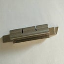
Step 8: Construction: Stage 6 - Making the Locking Pin


The locking pin is a ½” dowel with a wedge cut out in the middle section. The idea is that the beam can just slip over the wedge at its deepest position but not elsewhere. This means that once the beam is moved into position, you can tap the pin to engage the wedge against the base of the beam, locking it in place.
I stuck two short lengths of ½” square section different colored wood together to make it more interesting and to differentiate the two ends. As explained earlier, the pieces are stuck end grain to end grain with epoxy resin. The overall length of the work piece is about 3”. Unless you use a ready made dowel, you have to turn the square section work piece or to round off its corners. I don’t have a lathe so I used a ¼” radius rounding off bit on my router mounted on the router table and made four passes to round off each corner in turn. Before you do the same, take the trouble to test rout a similar sized scrap first. If the rod does not come out truly round trim the router cutting width and depth and test again. Insert your dowel into the lock pin hole of the fence. It should be a smooth but loose fit. If it is tight use a short 3/8” dowel with stuck-on fine sandpaper to open the hole slightly wider. Insert your dowel into the lock pin hole until about ½” sticks out from each side. You will be able to see part of the dowel at the base of the beam mounting hole. Take a sharp pencil and mark the exposed section of the dowel inside the big hole from both faces of the fence. You may now decide which end you want to indicate “lock” and which “unlock”. I chose the darker end as “lock”. If you do the same follow the rest of this paragraph. If not you will have to start your cut from the other end. With a trim saw, make a shallow cut to the depth of the pencil mark near the light color end of the dowel, about 1/8”. Then securing the dowel in your bench vise use a ¾” or 1” chisel, bevel down, to pare a wedge starting at about ¾” to 7/8” from the other end. Make shallow curved cuts until you can insert the beam into the fence with the pin in place. This is likely to be when you have cut the wedge close to the pencil lines. Stop paring once the beam can freely slide in. Now smoothen the wedge slope with sandpaper. Try tapping one end and then the other end to see that the locking and unlocking actions are smooth. Cut a small semicircular piece of felt, ½” wide and 1/8” tall and attach this to the end of the wedge cutout (see picture). This prevents the wedge from denting the beam when the pin is tapped hard to unlock. With the beam locked, mark off the ends of the pin ¼” from the side of the fence. Take out the pin and cut off the excess. Chamfer round the ends.
Step 9: Calibration and Finishing


Now that all the parts of the marking gauge are complete you can calibrate the instrument and attach the steel rule.
Assemble the gauge by inserting the locking pin and sliding in the beam. Install the knife with bevel outwards and shim on outside. Lock the beam so that the knife is about 2” from the fence.
Slide the precision rule in the routed recess in the beam and hold it temporary with masking tape at both ends. Now release the beam and move the fence to the 2” position indicated by the steel rule. Lock the beam. Take a piece of scrap board and use the gauge to mark a line across the grain. Measure this line from the edge of the board with an accurate ruler. If this is not exactly 2” you will need to shift the precision rule and try again. If necessary you may need to lift one end of the steel rule out of the groove in order to do so. Once it matches exactly, make a sharp pencil mark on the beam at the 2” point. Remove the steel rule and disassemble the beam from the fence. Replace the steel rule in the inlay groove and align the 2” point with your pencil mark. If one end or the other of the rule does not fit into the groove you will need to use a chisel and lengthen the groove to accommodate. Finally attach the steel rule to the beam in its groove with two-sided tape.
The marking gauge is now essentially finished. Use fine sandpaper to remove any sharp corners or minor blemishes and pencil marks. Finish the wood with several coats of furniture oil. I used tung oil but any good quality wood finishing oil will do. The oil is more for protection than for looks. The wood will take on a semi-gloss finish and that is fine. Finally polish some furniture wax onto the beam.
Happy marking!

Participated in the
Wood Contest 2016


