

Introduction: ATtiny Programmer Board (ArduinoUNO As ISP)


Additional information and document update here on my site:
https://www.mischianti.org/2019/08/02/attiny-progr...
ATtiny13/ATtiny13a/ATtiny25/ATtiny45/ATtiny85
I really like the ATtiny and programming it, so I built a simple board to use Arduino UNO as ISP in a faster way.
With the original Arduino UNO, there is a little variant because compatible one have another 5v VCC over RESET pin, Arduino UNO has IOREF instead, but don't worry look at the schema to make the simple change.
Step 1: Schema

In github project you can find the fritzing file with simple examples and schema.
Other solution is to export this board and send it to https://www.pcbgogo.com?code=y .
Step 2: Material

I use a perfored board.
To switch Voltage (to use 3.3v or 5v) and to enable test LED, I use a smd on/off button instead of a pin with a jumper.
The board is double sided so I can attach pin and components up and down the board.
AmountPart TypeProperties
- 1 Arduino Uno (Rev3) tipo Arduino UNO (Rev3)
- 1 Electrolytic Capacitor capacitance 10µF
- 1 Ceramic Capacitorcapacitance 100 nF
- 1 IC Holderpin spacing 300mil; pins 8
- 1 Green LED package 3 mm [THT]; colore Green (570nm); leg yes
- 1 Yellow LED package 3 mm [THT]; colore Yellow (595nm); leg yes
- 1 10kΩ Resistorresistenza 10kΩ; tolerance ±5%
- 2 220Ω Resistorresistenza 220Ω; tolerance ±5%
- Generic male header package THT; form ♂ (male); hole size 1.0mm,0.508mm; pin spacing 0.1in (2.54mm); pins 8; row single
- Generic female headerpackage THT; form ♀ (female); hole size 1.0mm,0.508mm; pin spacing 0.1in (2.54mm); pins 4; row single
Step 3: ATtiny13a Variant
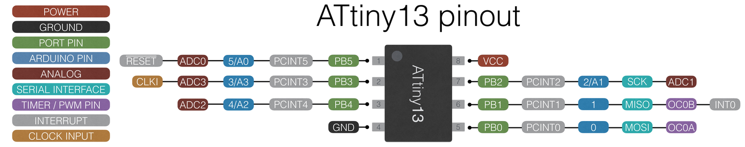

I buy ATtiny13a very low cost IC (less than 0.5€), with 4 analog pin and 2 PWM/TIMER PIN.
Step 4: Board V01

First version of board with no led indicators.
This version work only with fake Arduino.
Fritzing here.
Step 5: Board V01 (Original ArduinoUNO)

As you can see for Original Arduino uno you must add a wire to give 5v voltage to switch.
Fritzing here.
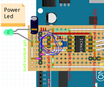
Step 6: Board V02 (power Led)

Add green led to control if board have power supply.
Fritzing here.
Step 7: Board V03 (test Led)

I add a very usefully test led, to check if all is connected correctly.
Fritzing here.
Step 8: Board: Voltage Jumper
ATtiny can work at various voltage so I insert a jumper to select ATtiny operating voltage 3v or 5v power supply.
Step 9: Board: Test Led Jumper

To test if It's all ok on board I add a test led that can be activated by that jumper.
Step 10: Board: Reset Capacitor

To prevent reset when upload code It's important to add a capacitor to reset pin of Arduino.
Step 11: Board: Voltage Capacitor and Reset Resistor

Other important thing is the capacitor to stabilize the voltage and pullup resistor to reset pin of ATtiny.
Step 12: Assembled Board
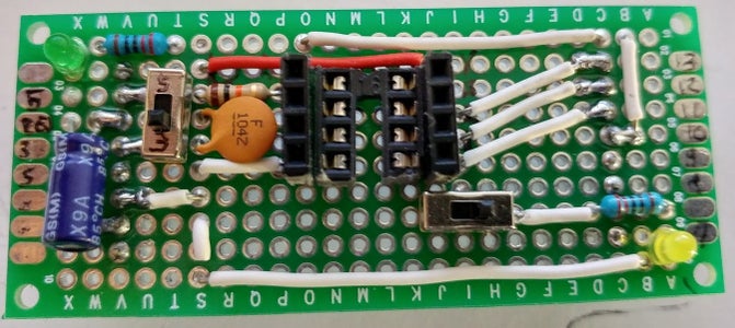
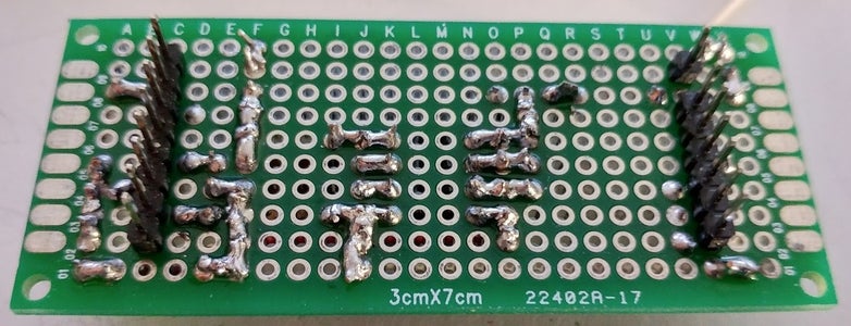

The realization is quite simple and the result is very usefully.
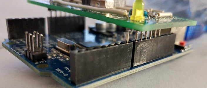
Step 13: How Board Fit on Arduino
Mount board on Arduino.
Step 14: How to Program an ATtiny: Prepare ArduinoUNO to Use It As ISP
- In Arduino IDE select ArduinoUNO board (Tool --> Board --> ArduinoUNO - Strumenti --> Scheda --> ArduinoUNO);
- Than open ArduinoISP example file (File --> Examples/Esempi --> 11.ArduinoISP --> ArduinoISP);
- Upload Arduino (Sketch --> Upload/Carica);
- Close IDE.
Step 15: Add Support for ATtiny: ATtiny13/ATtiny13a
- Open the Arduino IDE;
- Open the File > Preferences menu item;
- Enter the following URL in Additional Boards Manager URLs: https://mcudude.github.io/MicroCore/package_MCUdu... ;
- Open the Tools > Board > Boards Manager... menu item;
- Wait for the platform indexes to finish downloading;
- Scroll down until you see the MicroCore entry and click on it;
- Click Install;
- After installation is complete close the Boards Manager window.
Step 16: Add Support for ATtiny: ATtiny25/ATtiny45/ATtiny85
- Open the Arduino IDE;
- Open the File > Preferences menu item;
- Enter the following URL in Additional Boards Manager URLs: https://raw.githubusercontent.com/damellis/attiny... ;
- Open the Tools > Board > Boards Manager... menu item;
- Wait for the platform indexes to finish downloading;
- Scroll down until you see the MicroCore entry and click on it;
- Click Install;
- After installation is complete close the Boards Manager window.
Step 17: How to Program an ATtiny: Upload to ATtiny
- Attach board to ArduinoUNO;
- Insert ATtinyXX;
- If the board is v03 than activate test led otherwise using a breadboard and take VCC from upper right pin of attiny and GND to down left pin, than connect 0 pin (down right) to a led (on next video);
- Select board with correct setting and PORT (Tools --> Board/Strumenti --> Scheda);
- Select Arduino as ISP (Tools --> Programmer --> Arduino as ISP/Strumenti --> Programmatore --> Arduino as ISP);note: Arduino as ISP is different from ArduinoISP.
- Upload program (Sketch --> Upload from programmer / Schetch --> Carica tramite un programmatore).
Step 18: Sample Sketch
If the board is v03 than activate test led otherwise using a breadboard and take VCC from upper right pin of attiny and GND to down left pin, than connect 0 pin (down right) to a led (on video).
A simple scketch to upload to ATtiny
#define PIN 0
void setup()
{
  pinMode(PIN, OUTPUT);
}

void loop()
{
  digitalWrite(PIN, LOW);
  delay(500);
  digitalWrite(PIN, HIGH);
  delay(500);
}
Step 19: Thanks
In github project you can find some additional info and schema.

Participated in the
Arduino Contest 2017


