

Introduction: (Another Not So Mini) Millennium Falcon Popsicle Stick Model


Oh what a difference a long weekend makes!
Hello everyone, this next project details the steps done to make the fastest hunk of junk in the galaxy - a Millennium Falcon mini popsicle stick model.
Manufactured by Corellian Engineering, the light freighter became the most iconic spaceship of the Star Wars saga with Han Solo and Chewbacca, the most famous owners of the ship.
The project to fabricate the Falcon was planned more than a year ago with Instructable member and a good friend of mine, Blaise_Gauba providing the URLs for the initial 3D model. The same images were some of the ones used for the front, side and back reference profiles for this project.
The build consisted of three major sub-assemblies - The Middle, Top and Bottom Hull sub-assemblies. The real challenge for this project was in fabricating the top and bottom hull of the Falcon due to huge size of the ship. The build depleted my entire stock of tongue depressor-sized popsicle sticks that I had to run to a local drug store to replenish the materials to finish the project.
And unlike my previous projects with an average of just 6 steps to complete, this build consists of a staggering 10 steps (not counting the intro, materials and tools and images/schematics)! This is my most difficult (and ambitious!) project yet! And I must say that I'm impressed by the end result.
Step 1: Materials and Tools


Unlike other popsicle stick projects, a lot of materials were used for this build. The middle hull sub-assembly consisting of the basic airframe were from thin coffee stirrers. Most of the materials for the top and bottom hull sub-assemblies were made with tongue depressor-sized popsicle stick models. All other parts were from my spares box, including toothpicks used for the quad blaster barrels and landing gear assembly.
Tools used for the build were as follows:
- Dremel 3000 with the following attachments:
- Dremel workstation and flex tool shaft
- Coarse and Fine Drum sander
- Fine disc Sander
- #118, #124, #125 and #193 High speed cutter
- Standard & reinforced cut-off wheel
- #83702, #84922, #85622 and #85602 Silicone Carbide grinding stones
- #953, #541, #911 and #932 Aluminum Oxide grinding stones
- #7134 diamond wheel point
- Xacto hobby knife with a #11 blade
- Fine tweezers
- Mechanical pencil
- Ruler
- Various plastic clamps
- Elmers White Glue
- Cutting mat
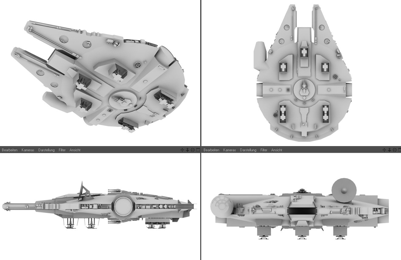
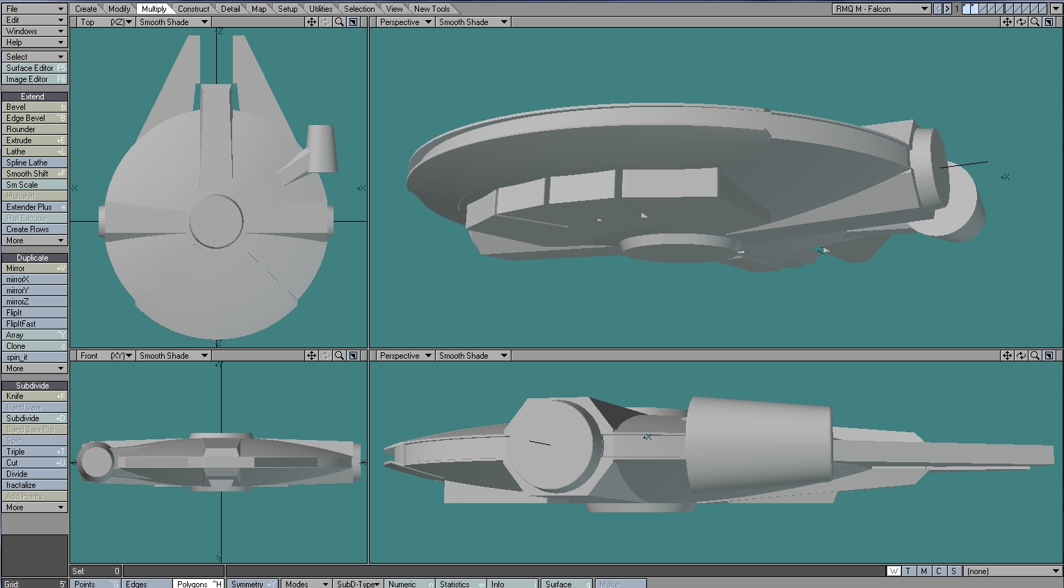
Step 2: Images and Schematics


As with other Star Wars spaceships, images and schematics for the Millenium Falcon there are countless sources from the world wide web. Keywords for this build for google and bing image searches are "millennium falcon". Additional searches were done to get details on the Falcon's landing gear, loading ramp and quad gun blasters.
The main schematic used were from the blueprints.com with images from media.moddb.com providing the bottom hull and gear assembly details. 3D models from povplace.com provided a general guide as to the main sections of the top and bottom hull sub-assemblies.
All images and schematics used as reference were from the following sites:
http://www.the-blueprints.com/blueprints-depot/sci...
http://media.moddb.com/images/members/1/186/185208...
http://www.povplace.com/index.php?t=2
https://gmd3ddesigns.files.wordpress.com/2012/03/f...
https://gmd3ddesigns.files.wordpress.com/2012/03/f...
http://2.bp.blogspot.com/-ugyIPUr8Wng/US31OIjgfjI/...
http://smallartworks.ca/Gallery/Starwars/sw.html
http://s222.photobucket.com/user/rogueleader1/medi...
http://www.modelermagic.com/wordpress/wp-content/u...
http://msfm.seryan.com/adolphe_d/millenniumfalcon-...
As with my previous instructables, I've included my Falcom .pdf plans that I actually used for the build. You can download the file Falcon planv2.pdf from this step.
Again, my eternal gratitude to the fine folks posting these images for guys like us to use as reference. Thank you very very much!
Attachments

Step 3: Middle Hull Sub-assembly


The build begins with the fabrication of the middle hull sub-assembly. The middle hull provided the basic, round shape of the Falcon and was used to guide the top and bottom hull fabrication. Thin wooden coffee stirrers were used for the frame of the middle hull sub-assembly.
The illustration in this step shows the fabrication of the Falcon's outline based on the top-view image from the blueprints.com schematic. Each side was carefully reinforced with wooden coffee stirrers to provide rigidity to the basic structure. Additional layers of scrap popsicle sticks were used to build up the edges of the basic structure. A gap in sides of the middle hull will mount the circular port and starboard docking rings for installation later in the build.
To further reinforce the skeleton, tongue depressor-sized popsicle sticks were glue on top of the entire structure. The flat 'roof' of the skeleton was sanded with a coarse drum sander attachment to conform to the round shape of the middle hull.
Step 4: Bottom and Top Hull Sub-assembly


And now for the hard part, fabrication of the bottom and top hull sub-assemblies.
I actually used two different approaches for the top and bottom hull. Although both sub-assembles consisted of four (4) layers of various combinations of laminated tongue depressor-sized popsicle sticks and regular sized popsicle sticks, I went with carving a round structure for the bottom hull. Lamination of the four (4) layers consisted of gluing each layer perpendicular to the previous layer to reinforce the entire structure. A hobby saw was useful in cutting a rough, round shape for the bottom hull.
Spare tongue depressor-sized popsicle sticks were carved into a circle for the top gun blaster turret mount. The round turret mount was used as a guide to determine the center of the bottom hull sub-assembly. Finally, after tracing the pattern for the gun turret mount on the round bottom hull, the entire sub-assembly was sanded using a combination coarse/fine drum sander attachment on a Dremel 3000. The bottom hull's shape now resembled Captain America's round shield.
The top hull was laminated and sanded initially as a square and carved into a round shape after cutting-out the gaps for the front concussion missile launcher, cockpit access corridor, port and starboard corridors and rear engine assemble. The parts cut-out from the top hull will be used later in the build for the side landing gear mounts.
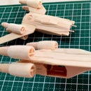
Step 5: Forward Mandibles & Top Rear Engine Housing


The forward mandibles housing the circular maintenance access bays were made from spare tongue depressor sized popsicle sticks. Each mandible consisted of three (3) layers laminated together. Lamination was done after the two (2) circular access bays were drilled onto the top and bottom layers. Another challenge for the three (3) laminated layers was to make the middle layer at a slightly smaller scale to highlight the distinctive top and bottom layer.
To make the circular access bays, a pilot hole was drilled using a #125 then a #124 high speed cutter attachment on a moto tool. The pilot hole was finished using a #953 aluminum oxide grinding stone attachment.
As illustrated in the detailed steps, each layer consisted of two parts to cover the entire width of the mandible.
The top rear engine housing was made from four (4) layers of sandwiched, tongue depressor-sized popsicle sticks cut and shaped using the blueprints.com pattern as guide. This sub-assembly will eventually be glued to the gap in the rear top hull sub-assembly.
Step 6: Cockpit and Heat Vents


The cockpit for the Millennium Falcon consisted of a staggering eleven (11) layers of laminated tongue depressor sized popsicle sticks glued into a dowel-shaped single piece and shaped based on the schematics from the blueprints.com.
Fabricating the cockpit consisted of a lot of sanding and shaping using a combination of coarse/fine drum and disk sander attachment on a moto tool. The 'finished' cockpit was detached from the single laminated piece using a reinforced cut-off wheel attachment.
Commercially available wooden dowels were too small for the heating vents so I had to fabricate one to match size of the illustration in the schematic. For the six (6) distinctive circular heating vents on top of the rear top engine housing, four regular sized popsicle sticks were glued and sanded to form a single wooden dowel.
A pilot hole was carefully drilled at the end of the dowel using a #125 and a #124 steel cutter attachment. The hole was finished with a #953 aluminum oxide attachment. Each heating vent was 'sliced' off the end of the dowel with the use of a reinforced cutting wheel attachment.
Step 7: Cockpit Access Corridor, Top Side Access Corridors, Top Concussion Missile Launcher and Radar Dish


The cockpit access corridor, top side access corridors and top concussion missile launcher were customized using various spare popsicle sticks to fit the gap created in fabricating the top hull. As with the top hull, all the parts consisted of four (4) laminated layers. As shown in the illustrations for this step, each major piece should fit snugly into the gaps made on the top hull sub-assembly.
The radar dish was carved directly from the leftover dowel from the cockpit canopy step (Step 6). After a pilot hole was made using a #953 aluminum oxide grinding stone attachment, a #911 aluminum oxide grinding stone and finally a round grinding stone attachment was used for the concave depression of the dish. After detaching the dish from the dowel using a reinforced cutting wheel attachment, the dish was finished with a coarse/fine disk sander attachment on a moto tool.
The Millenium Falcon was finally taking shape after all the completed pieces were test-fitted to the top hull.
Step 8: Top & Middle Hull Assembly


The flat top hull sub-assembly, similar to the bottom hull, was carved into a disk shaped piece using a combination of coarse/fine drum sander attachment on a Dremel 3000.
Illustrations show that the cockpit access corridor assembly occupies a portion of the top and middle hull sub-assemblies. The Captain America shield-shaped top hull was test-fitted to the middle hull and a mark made for the cockpit access corridor assembly. A gap was cut from the middle hull using a reinforced cutting wheel attachment.
The top and middle hull sub-assemblies were glued and allowed to dry thoroughly. The forward mandibles, top concussion missile launcher assembly, cockpit access corridor, top port and starboard access corridors and top rear engine housing were glued to the gaps in the completed top and middle hull.
The six (6) circular heating vents were glued on top of the rear engine housing using the top-view illustration of the blueprints schematic as reference.
Finally, additional white glue was added to the major pieces to reinforce the bond.
Step 9: Radar Assembly and Bottom Blaster Cannon Mount


At last! A use for my commercially available dowel! Or so I thought...
Anyway, I initially sliced off a thin piece from the end of a dowel using a reinforced cut-off wheel attachment for the radar dish's hull mount. It turns out that the piece from the dowel was too small for the hull mount so I had to fabricate another circular mount from a spare regular-sized popsicle stick.
The radar dish's stand and dish mount were similarly cut from regular-sized popsicle sticks cut into shape with a standard cutting wheel and finished with a fine disk sander attachment.
The tiny center antenna was cut from a small dowel with a standard cutting wheel attachment.
The dish mount was glued to the back of the radar dish. The dish's stand and center antenna was added later.
The two (2) layer bottom blaster cannon mount was made from spare tongue depressor-sized sandwiched together with white glue and finished with a coarse/fine drum sander attachment.
Step 10: Bottom Hull & Landing Gear Mounts


Similar to the top hull sub-assembly, gaps for the bottom rear engine housing, bottom side access corridors and bottom concussion missile launcher were cut from the bottom hull using a #118 steel cutter attachment (to drill a pilot hole) and a reinforced cut-off wheel attachment. The slot for the middle landing gear housings were made using a #85622, #83722 silicon carbide grinding stone and a #193 high speed cutter attachment. The two (2) middle landing gear housings should fit snugly into the slot later on in this step.
Detailed pictures shows five landing gear assemblies for the Millennium Falcon. Two (2) larger gear assemblies were mounted at the bottom rear engine housing, two (2) at the middle landing gear mounts and one (1) below the bottom concussion missile launcher.
Excess parts from the top and bottom hull sub-assembly were recycled for the bottom rear engine housing, middle landing gear housings and bottom concussion missile launcher.
Another layer of scrap popsicle sticks with square cut-outs for the landing gear assemblies were added to the bottom rear engine housing and middle landing gear housings. A smaller piece with a similar square cut-out was added to the bottom concussion missile launcher.
The bottom thrust vector plates mounted at the rear of the engine housing were made from scrap tongue depressor-sized popsicle sticks cut and sanded using a coarse/fine drum sander attachment. Another piece was added to extend the plates to match the level of the plates on the top hull sub-assembly.
Since the popsicle stick model of the Millennium Falcon depicts the starship on a landed position, I opted to show a deployed loading ramp on the starboard side (cockpit side of the ship). It was for this reason that only the bottom port access corridor was made from spare tongue depressor-sized popsicle sticks. Similar to all bottom side components, the bottom port access corridor was made from four (4) layers of laminated popsicle sticks cut and shaped using a coarse/fine drum sander attachment.
Finally all bottom-side components were glued to the bottom hull at the pre-cut spaces of the bottom hull sub-assembly.
Step 11: Top and Bottom Hull Assembly


The top/middle hull sub-assembly was glued to the bottom hull sub-assembly completing the assembly of tow (2) of the major parts for the build.
For the port and starboard docking ports (and escape pods), a portion of the leftover dowel from the cockpit canopy build was sliced off using a reinforced steel cutter. A depression at one end was made using a #932 aluminum oxide grinding stone attachment. A slice from a smaller dowel for the Falcon's escape hatch was glued at the center of to the depression. The completed port docking port was glued at the end of the port access corridor.
For each side of the starboard corridor, three (3) layers of scrap popsicle sticks were used. Each piece was angled using a coarse/fine drum sander attachment and glued to the open side of the bottom starboard corridor. The gap created will serve as the entrance to the boarding ramp to be installed in the later stages. To complete the starboard access corridor, a small scrap of popsicle stick to mount the starboard docking port was glued at the end of the bottom starboard corridor with the starboard docking port finishing the assembly.
Next, the completed hull assembly was laid on top of the schematics and patterns on the serration drawn on the hull. To model the serrated edges of the Falcon's top and bottom hull, a coarse disk sander attachment was used on each serrated mark. Details on the hull's surface was etched using a #83702 silicon carbide grinding stone attachment.
Lastly for this step, the bottom gun mount was glued to the center of the bottom hull. A depression for the quad blaster was made using a round grinding stone attachment.
Step 12: Quad Gun Blasters, Landing Gear Assemblies and Other Final Details


QUAD GUN BLASTERS
The top and bottom quad gun blasters consisted of three main components; the semi-circular gun mount, the four (4) piece gun barrels and the gun's receiver.
The semi-circular gun mount was created using the same steps in making the circular heat shields. A hole was drilled at the end of the dowel and thinly sliced using a regular cut-off wheel attachment. The semi-circular gun mount was finished using a fine disk sander attachment on a moto tool.
The four quad barrels were from thinly shaped toothpicks with the wider end sliced using a regulat cut-off wheel attachment. The crescent shape of each of the barrel's ends where made using a fine disk sander attachment.
The gun's receiver was made from a tiny laminated scrap popsicle stick. The gun barrels were glued, one at a time at one end of the receiver. The completed quad blaster assembly was set aside to dry completely.
LANDING GEAR ASSEMBLIES
Next to the gun barrels, the landing gear struts were similarly the tiniest parts of the build. Other main components of the landing gear assemblies were the circular landing pad connectors and the rectangular landing struts mount.
I started with fabricating the landing pads from scrap tongue depressor-sized popsicle sticks. Images show that the three (3) of the pads were shaped like wide rectangular crosses and the two (2) rear pads rectangular crosses joined together. I used a fine disk sander to cut notches at the ends of each rectangular piece.
The circular landing pad connectors were sliced from small, commercially available dowels.
The tiny, rectangular landing strut mounts were from scrap, wooden coffee stirrers, cut into size with an X-acto knife.
The circular landing pad connectors were first glued on top of each landing pad with the rectangular landing struts mount glued after. Each landing gear strut was glued, a pair each per landing pad (except for the front, middle landing gear which only has one strut).
LOADING RAMP
The loading ramp consists of three (3), tiny components; the ramp, the side, loading strut mounts and the cylindrical loading struts.
The ramp was made from scrap, tongue depressor-sized popsicle stick. The size of the ramp was patterned after the gap of the lower starboard, access corridor.
The two (2), tiny loading strut mounts were from spare popsicle sticks, cut using an X-acto knife.
The two(2) cylindrical loading struts were from wooden toothpicks cut and shaped using a #85602 silicon carbide grinding stone and a fine disk sander attachment.
The loading strut mounts were glued at the end sides of the ramp. The ramp and loading struts were set aside until the landing gear was installed. This was to ensure that the height of the ramp is the same as the height of the Falcon in 'landed' mode.
COMPLETING THE MODEL
The final assembly begins with installing the top gun blaster assembly to the top hull of the Falcon.
The semi-circular gun mount was glued on top of the top gun mount depression. A tiny scrap popsicle stick was used to brace the semi-circular gun mount on top of the depression to make it appear that the mount is suspended.
The quad gun blaster assembly was glued at the apex of the semi-circular gun mount next. Similarly, a tiny scrap popsicle stick was used to brace the quad gun blaster assembly to make it appear that the quad gun blaster is suspended.
The radar dish assembly was then glued on the front, left side of the top hull with the radar dish facing towards the front of the falcon.
With the top quad gun blaster assembly and the radar dish in place, the landing gears were installed next.
The front landing gear was glued below the slot made at the bottom concussion missile launcher. The four (4) layer excess part left-over from the top hull build was used to prop up the Falcon while the glue of the front landing gear sets.
The two (2) rear landing gear assemblies were glued at the the slots made at the bottom engine housing assembly.
With the front and rear landing gear assemblies in place, the loading ramp was glued to the end of the gap of the lower starboard, access corridor. The two(2) cylindrical loading struts were glued at the inside walls of the corridor. I made sure that the end of the loading struts are in contact with the loading strut mounts of the loading ramp.
With the loading ramp, front and rear landing gear assemblies in place, the port and starboard side landing gears were glued next.
The landing gear doors were made from spare, tongue depressor-sized popsicle sticks cut using an X-acto hobby knife. Doors for the rear landing gear assemblies were cut larger than the front and middle landing gear assemblies. The doors were glued front and aft for the front and middle landing gear assemblies and port and starboard for the rear landing gear assemblies.
By this time, the landing gears and loading ramp must be able to support a 'landed' Millenium Falcon.
For additional details on the top hull, spare, regular-sized popsicle sticks were used for the deflector shield projector. The tiny, rectangular pieces were glued on top of the mandibles where the mandibles meet the main hull of the ship.
Tiny, triangular fuel drive stabilizers (four for the top hull and four for the bottom) were cut from spare popsicle sticks and glued at regular intervals on the top and bottom edge of the vehicle's main propulsion drive system.
Finally, the bottom gun blaster assembly was glued to the bottom mount.
And there you have it! The fastest ship in the rebel fleet!
Till the next project, The Force Awakens!

First Prize in the
Sci-Fi Contest


