

Introduction: Arduino "Atomic" Grandfather Clock


I wanted an electro-mechanical Grandfather clock that did not require winding and correcting every week but that looked and sounded as original as possible.
see my site here Longcase Clock Website
This Instructable shows how to add Arduino controlled analogue movements to a Grandfather (longcase clock/tallcase clock) or any other clock case where analogue displays are required.
The Arduino gets the time code from the DCF77 transmitter in Germany and will work for any location in range of the transmitter including England.
The code can be used for any other transmitter in the world by changing the decoder library and modifying the code to suit.
This clock has 3 analogue dials, hours/mins, seconds and also a Moon phase dial. There is a secondary 4x20 LCD display under the hood to give full info on the clocks status. The clock controls are mounted on the same vero board as the LCD display.
The pendulum is electric and uses a heavy duty pendulum drive powered by a single 1.5v battery. This battery will last over a year.
As the clock is synchronized to the DCF77 transmitter as are all my clocks I use ticking sounds and full Westminster chimes from other clocks on my system.
Step 1: Video
Short 2 minute video showing some of the clock functions.
The clock ticking and chiming is controlled by other clocks on the system and can be turned off or on independently.
The 1 second ticking comes from my Dial Clock Dial Clock and chimes from my calendar clock .
or you can view Dial Clock Instructables here Dial Clock .
Step 2: Parts Required
Clock case.
Case
The empty longcase clock case was purchased from Ebay and is probably from the early 1900s.
Dial
The dial is made from scratch using a sheet of aluminium for the dial plate and then chapter rings and spandrels were purchased from clock suppliers/Ebay. I had to design custom lettering for the Moon dial and this was applied to a spare seconds chapter ring using Lazertran paper.
Clock movements
2 x standard UTS movemants for the seconds and Moon phase and a radio movement for hour/minutes. All movements have their stepper motors isolated so the Arduino can control them.
Arduino
I used a selfbuilt Arduino Uno on a veroboard but a prebuilt Uno will be fine as well. You will also need the electronic components and switches as per the schematic.
Pendulum drive
The trunk to my clock glazed and I wanted the pendulum to move so I used a heavy duty pendulum drive. If your case is closed then this will not be required.
Weights & Chains
Again as the trunk is glazed I added false weights and chains.
Step 3: The Case


The clock case is 2.1m or 6' 10" high x 0.415m or 1' 4" wide x 0.21m or just over 8" deep and is made of Oak. The removable hood will take an 8" breakarch dial and would have been accessed via the hinged door. The case has a fully glazed door so would probably have had decorative brass weights and chains along with a brass pendulum bob. I have fitted false weights and chain from an old clock and an electric motor to drive a false pendulum.
The Hood pic 3 slides off the clock after disconnecting the 5volt power plug and DCF77 input wire.
Battery backup keeps the clock running while disconnected.
There is plenty of space in the hood for circuit boards, controls and displays.
Step 4: Dial Plate


The clock had no dial so a complete dial was made up from scratch.
Picture 1
Using the wooden dial surround as a template and leaving a 20mm overlap, the dial plate is cut from a sheet of aluminium.
Hole are drilled to take miniature bolts, 4 for the hours/mins chapter ring, 2 for the moon and seconds chapter rings and 2 each for the dial, breakarch and top centre spandrels. Holes are also drilled to take the hand shafts from the 3 modified movements. In the original clock the dial would have been mounted in the hood separate from the dial surround door to enable the time to be set from the front of the dial by moving the minute hand. On this clock the hands are set by remote switches so the dial can be screwed to the wooden dial surround. Holes are drilled around the edge to take these screws. The aluminium dial plate in the animation is shown in it's unpolished state.
Picture 2
Brass Spandrels can be purchased from clock maker suppliers/Ebay. To give an aged effect I sprayed them with black paint then rubbed the black paint off the highlights.
Picture 3
Once all dials and spandrels have been test fitted the aluminium dial plate is given a final rub down in one direction only to give a grain effect and a clear lacquer is added.
Picture 4
Rear view of dial showing bolts fixing chapter rings and spandrels and clock motor modules fixed to mounting bars.
The mounting bar for the seconds and Moon dial is set back from the dial plate to keep both seconds and Moon hands near the chapter rings. Note the dial plate is shown semi transparent to show locations of chapter rings and spandrels on the front of the dial plate.
Step 5: Chapter Rings


The Moon chapter ring is made from a re-labelled seconds chapter ring. The seconds lettering is removed with wire wool then the moon lettering is printed out on Lazertran Paper applied and then lacquered over.
The hour & minute chapter ring is from an old clock dial and was already drilled out for mounting bolts.
Moon
Picture 1
The moon dial shows the current age of the moon with a new moon at 0 a full moon at around 15.
The actual moon age in days and hours is shown on the LCD display while the moon dial moves a half segment in half a moon day.
Picture 2
This clock displays the Synodic month and this varies as the Earths orbit around the Sun and the Moons orbit around the Earth are elliptical.
The actual rate of Lunation, the time from new Moon to full Moon is between 29.18 to 29.93 days. The long term average is 29.530587981 days and this number is used by this clock to determine the Moons age. The Moon dial is mechanically split into 59 segments (actually 60 but the code jumps the 60th segment) with each segment being 1/2 a Moon day. The Arduino code steps through exactly once per second and adds 1 to the Moon Count every second. A Lunation takes 29.530587981 days or 2551442.877 seconds. I calculated this by the following. 29 days = 29x24hours = 696 hours 696 hours = 696x60minutes = 41760 minutes 41760 minutes =41760x60seconds = 2505600 seconds so 29 days = 2505600 seconds 0.530587981 days = 0.530587981x24hours = 12.73413247 hours 12.73413247 hours = 12.73413247x60minutes = 764.0479483 minutes 764.0479483 minutes =764.0479483x60seconds = 45842.8769 seconds so 0.530587981 days = 45842.8769 seconds add the two together 2505600 seconds + 45842.8769 seconds = 2551442.877 seconds so 29.530587981 days = 2551442.877 seconds As the Moon display steps 59 times in a Lunation each step is 2551442.877 seconds / 59 steps = 43244.79452 seconds I have rounded this up to 43245 seconds. Every time the Arduino Moon count hits 43245 it advances the Moon display by 1 segment or 1/2 a Moon day. At the end of the Lunation the Arduino steps 1 extra segment to return the Moon display to 0 days.
Seconds
Picture 3
The seconds chapter ring was purchased from Ebay and only needed holes drilled for the mounting bolts.
Hours/Minutes
Picture 4
The hour and minute chapter ring can with four pre-drilled holes where it had been mounted in it's original dial.
Step 6: Movements


Analogue Movements
Picture 1
There are three analogue movements one each for the Hours/Minutes, Moon & Seconds displays. All the analogue displays are driven by Lavet type stepping motors. The motors are sourced from 2 x U.T.S. quartz clock movements for seconds and moon display and a U.T.S. DCF77 Radio movement for the hour and minutes display. The motor requires very low current to drive it and can be driven direct from the Arduino output via a trimmer resistor. The resistor is used to adjust the current to the motor so it works without being over driven. The motor is driven by reversing the polarity to the drive coil which causes the permanent magnet toothed rotor (in red below) to turn 180°. The toothed rotor will continue to turn in the same direction each time the drive motor polarity is reversed. 2 output pins from the Arduino are used to pulse the drive motor with 1 pin always the opposite to the other.
The Lavet motor in the U.T.S. quartz clock movements drives the attached hand 1/60th of a turn (1 second) on each activation while the Lavet motor in the U.T.S. DCF77 Radio movement drives the min hand (the hour hand is geared down from this) 1/240th of a turn or 15 seconds.
Hacking the movements
In order for the Arduino to control the drive motors the 3 movements have to have their motors isolated from their onboard drive circuits.
U.T.S. DCF77 Radio Clock Movement Hack
Picture 2&3
Carefully prise the movement apart and remove the top and bottom case sections.
Picture 4
This will leave the movement PCB, DCF77 aerial and motors
Picture 5
Turn the PCB over so the solder side is visible.
Desolder the DCF77 aerial from it's solder pads as it is not required.
There are 2 drive coils on this movement, 1 for seconds and 1 for hours and minutes. Locate the 2 drive coil solder terminals, marked 1 and 2 above. 1 is hour and minutes 2 is seconds. Cut one of the tracks to the minute and hour solder terminal to isolate the drive coil. Only the hour and minute coil is required so wires are soldered to coil contacts 1 and 1. Take these 2 wires through the clock movement and out into the battery bay.
Picture 6
Solder the 2 wires from the hour /minute motor to the "Clk Motor Coil" terminals on the Lavet type stepping motor driver board.
Locate the PCB/motor board back in the 2 case sections making sure the wires do not foul the case and clip the case back together. The Lavet type stepping motor driver board is "hot melt" glued in place.
U.T.S. Quartz Clock Movement Hack
Picture 7,8&9
Carefully prise the movement apart and remove the top and bottom case sections.
The Quartz PCB and motor section can then be lifted out as 1 part.
Picture 10
Turn the Quartz PCB and motor section over to reaveal the solder side of the PCB.
Cut one of the tracks to the motor coil to isolate it. Solder wires to each of the coil solder pads and take them out of the clock into the battery bay.
Picture 11
The Lavet type stepping motor driver board is "hot melt" glued in place.
Step 7: LCD Secondary Display
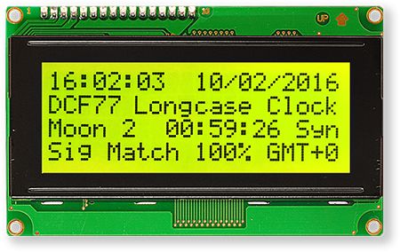
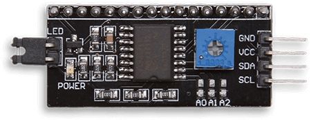
The LCD (picture 1) is a yellow 4x20 with an I2C module (picture 2) soldered to the board allowing 2 wire control by the Arduino.
The LCD Display shows the following information
Row 0 Current time and date should be identical to the hours, minutes and seconds dials.
Row 1 Clock Name My Name & software version no 1 second clock total missed (fast) pulses and extra (slow) pulses. When the clock drifts and then resets a second ahead of clock time. An extra 1 second pulse (slow) is required to keep correct time on 1 second clocks. When the clock drifts and then resets a second behind clock time. A 1 second pulse is missed (fast) to keep correct time on 1 second clocks. The total is reset at 06:10 in the morning. This row also displays the Summer/Winter advance retard information when the clock is correcting the hour and minute dial.
Row 2 This row shows the Moon age in Days, Hours, Minutes & Seconds. This row also displays decoding status Syn, Lck, Dty and Fai
Row 3 This row shows the received signal accuracy in %, the Auto Tuned Quartz crystal frequency accuracy down to 1 Hz and the actual Auto Tuned Quartz crystal tuned frequency in Hz. Summertime/wintertime indicator GMT/GMT+1
Step 8: Controls

There are 14 control switches in the clock controlling various functions.
SW5 Arduino reset Non locking switch that performs a reset on the Arduino.
SW1 Hour/Minutes dial On/Off Locking switch mounted in the hour/minutes motor housing and provides On/Off control of the hour/minutes display.
SW6 Moon Phase Dial On/Off Locking switch mounted in the Moon dial motor housing and provides On/Off control of the Moon phase display.
SW14 Seconds Dial On/Off Locking switch mounted in the Seconds dial motor housing and provides On/Off control of the Seconds display.
SW12 Seconds set Double pole three position non locking switch with centre off. When SW13 is set to Manual SW12 steps the second hand when moved from the 2 step positions.
SW13 Seconds Control Double pole three way locking switch. Down Auto -Arduino controlled, Middle seconds off and up Manual- allow seconds stepping by SW12.
SW15 LCD display On/Off Locking switch mounted on the main board. Signals the Arduino to turn on/off the LED backlight on the LCD display and LCD display itself.
SW11 Summer Advance (picture 1) Non locking switch that when pressed starts the summer advance of the hour/mins dial. The hour/mins dial is advance by 1/4min every 1 seconds. The LCD display changes to show the number of Summer Advance pulses sent. On 0,15,30 and 45 seconds the advance count is not incremented to allow for normal hour/mins drive pulses (see looped animation below). This ensures that after 240 pulse counts the hour/mins clock is advanced exactly 1 hour. The LCD display reverts back to normal stepping every 15 seconds.
SW9 Winter Retard (picture 2) Non locking switch on main board. When pressed starts the winter retard of the hour/mins dial. On the next missed hour/min drive pulse @ 0,15,30 or 45 seconds the LCD changes to show "Winter Retard". Every time a drive pulse is missed the "Winter Retard" count increments by 1.
Once the "Winter Retard" count reaches 240 the LCD display reverts back to normal and the clock is advanced every 15 seconds as normal.
SW16 Hour/Minute SetLocking switch mounted on the main board. Advances the hour/minute dial by 15 seconds every second pressed.
SW7 Reset Moon Count Non locking switch on main board. When pressed resets the Moon day count and time on the LCD display to 0.
SW8 Moon Time Advance Non locking switch on main board. When pressed advances the Moon Time on the LCD by 24 mins and 25 seconds.
SW3 Moon Phase Advance Non locking switch on main board. When pressed advances the Moon day/phase once per second.
SW10 Moon Display Advance Non locking switch on main board. When pressed advances the Moon display dial once per second.
Step 9: Pendulum Drive


Picture 1
As this clock case has a glass trunk door the Pendulum is visible and to make the clock look like it is still mechanically operated an electric pendulum drive is added.
This heavy duty drive will dive a pendulum of 40" and weighing 8oz or more from a single D cell battery for over a year.
Instructions for the pendulum drive
INSTRUCTIONS FOR THE ISI HEAVY DUTY PENDULUM DRIVE
This heavy duty pendulum drive is the first of it’s kind. It was designed to operate a 40”pendulum that weighs 8 ounces for more than a year on one D cell battery. It is perfect for making low cost grandfather size clocks, but if you use your imagination, it will do so much more.
1. When opening the device, please note that there is a separate battery well with wires and a connector (figure B) that needs to be connected to the pendulum drive (figure C). In most cases it is best to mount the battery well above the pendulum drive.
2. This heavy duty pendulum drive has a very unique feature. The part of the device that powers the pendulum is actually “hinged” This means that if properly installed, your clock can actually be a few degrees out of level, from front to back, and still work properly. If you cut a 2” wide by 5 5/16” long hole in the board you are mounting this to (this is the measurement of the rectangle when looking at the back of the device), this will allow the hinged pendulum drive (figure A) to move back and forth if needed.
3. Both the battery well and the heavy duty pendulum drive were designed to be installed with screws. We do not supply the screws because the type of screw you use should be determined by the material you are mounting this device to. You will need six screws. The mounting positions for these screws are indicated in the drawing to the right.
4. Mounting tips please consider how far-behind the dial of your clock you want the pendulum to swing. You will need to attach the heavy duty pendulum drive to a board of some type that is hidden behind the dial of your clock. Please make sure that this board is installed so that this device can easily be made level.
5. Swing Adjustment: This device is operated by an electro magnet that is positioned between two magnets (D) that are on the pendulum arm. If the swing of your pendulum is too wide, then you can put a piece of tape over one or both of the magnets to reduce the width of the swing of the pendulum.
Pendulum picture 2
The wooden pendulum and brass bob are constructed from old clock parts.
Weights & Chains picture 3
To complete the clock false weights and chains are added and fixed to a wooden batten behind the hood.
Step 10: Main Board Layouts


Components are mounted on prototyping boards.
Picture 1 front and 2 back show Lavet type stepping motor driver board. One required for each motor, 3 in total.
Picture 3 front and 4 back show the main board with Arduino 328 microprocessor configured as an Arduino Uno, the control switches and LCD secondary display.
Full size main board front in zip file
Attachments

Step 11: Schematic
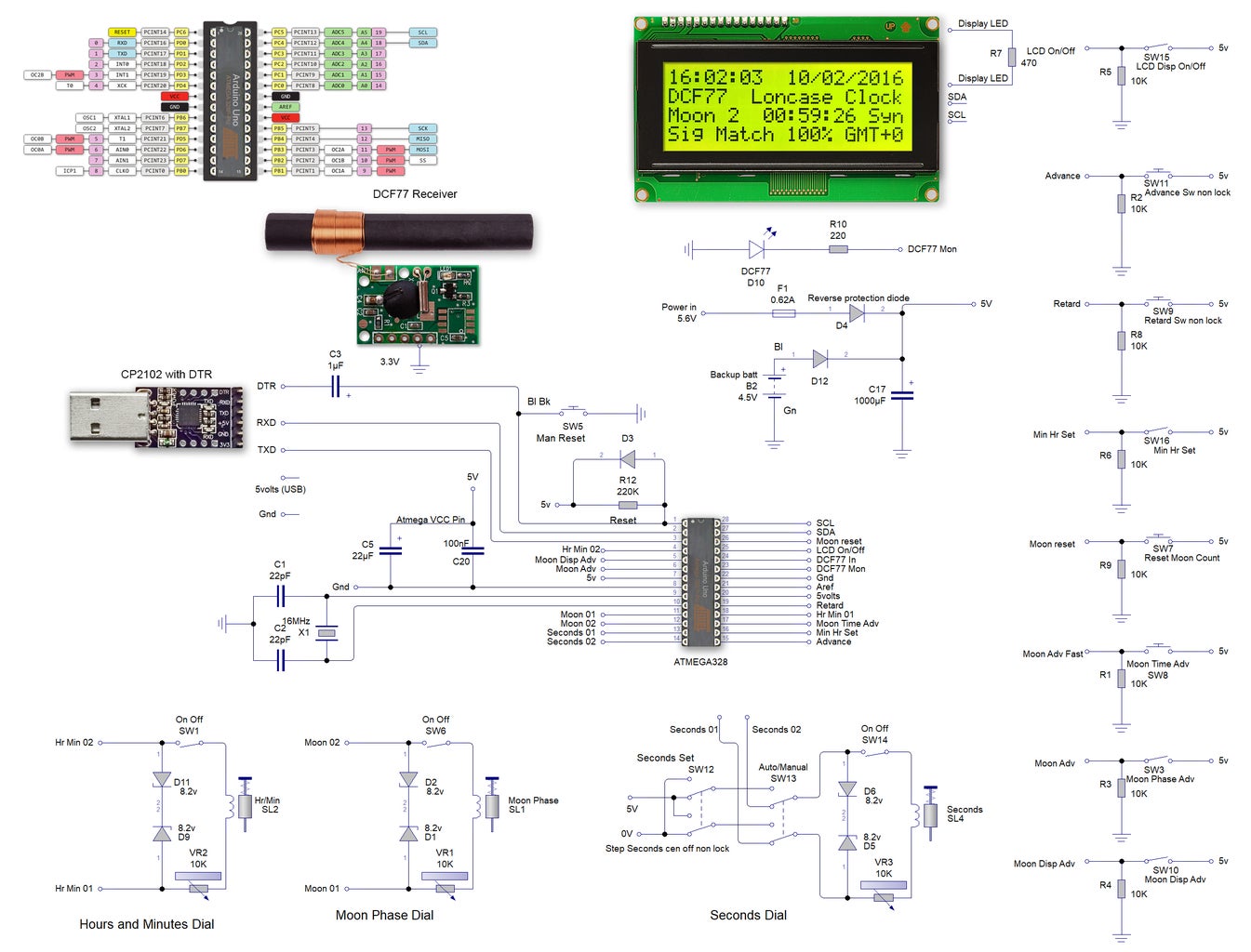
Picture 1 shows the schematic. If an Arduino Uno is used the diagram on the top left shows how the I/C pin connections translate to Arduino Uno connections.
Full size schematic in zip file
Attachments
Step 12: Code
This code Requires the following libraries
dcf77.h Note this clock uses Udo Kleins Release 3 library download here DCF77 Release 3


