

Introduction: Arduino Based Door Locking System


Electronic Door Look using Arduino
Presented here is an electronic locking system in which Arduino Nano plays the role of the processing unit. This circuit allows activation of an electronic door lock only on entering the correct password. It uses Arduino Nano to provide a keypad interface door lock for the front door. It is a keyless system where you can use your own personal code to enter your home with just a few simple pushes of some buttons. The keypad lock functions by entering secret code, which is user-programmable.
Step 1: Circuit Daigram

Circuit and working
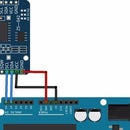
Using a microcontroller (MCU) cuts down on external components. The circuit comprises Arduino Nano board, transistors PN2222A (T1) and BD139 (T2), a 4x4 matrix keypad (S1-S16), solenoid lock and a few other components. The 4x4 matrix keypad is connected to Arduino digital pins D5 through D12. The keypad is simply an arrangement of 16 pushbutton switches in a 4x4 matrix form. Typically, a hex keypad will have keys for numbers 0, 1, 2, 3, 4, 5, 6, 7, 8 and 9, letters A, B, C and D, and symbols * and #. The hex keypad will have eight connection wires, through resistors R1, R2, R3, R4 and capacitors C1, C2, C3, C4, representing the rows and columns, respectively. The matrix-encoding scheme requires fewer output pins and, thus,
fewer connections that have to be made for the keypad to work. The schematic diagram of the electronic door lock system is shown in Fig. 2. Arduino receives parallel data from the keypad. Arduino software constantly scans the keypad to see if a button is pressed. Upon receiving a valid code input, digital pin D4 goes high and fires up the solenoid lock for five seconds. Transistor T2 is capable of supplying up to 1.5 ampere current to the solenoid. LED1 indicates
that the lock has been opened. Entering an invalid code causes it to blink a few times. Diode D5 protects the circuit from any back EMF that might be created when the lock is turned off.
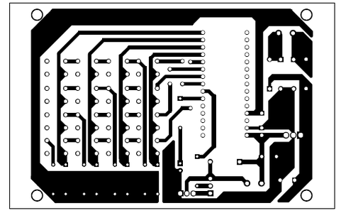
Step 2: PCB Design
Step 3: Components


