

Introduction: Arduino Based Pulse Induction Detector - Flip Coil


The Idea
Having build some metal detectors in the past with varying results I wanted to explore the capabilities of the Arduino in that direction.
There are some good examples of how to build metal detectors with the Arduino, some here as instructables. But when looking at them, they normally require either quite some external components for the analog signal treatment or the sensitivity is quite low.
When thinking about metal detectors, the main topic is how to sense the slight changes of voltage in signals related to the search coil. These changes are normally very small. The most obvious approach would be in using the analog inputs of the ATmega328. But looking at the specifications there are two basic problems: they are (often) to slow and the resolution is (in most cases) to low.
At the other hand, the Arduino is running at 16MHz and has quite some timing capabilities i. e. a resolution of 0.0625µS if using clock speed. So instead of using the analog input for sensing, the simplest way of sensing small dynamic changes in voltage is to compare the change in voltage drop over time at a fixed reference voltage.
For this purpose the ATmega328 has the neat feature of an internal comparator between D6 an D7. This comparator is able to trigger an interrupt, enabling precise event handling. Leaving beside the neatly coded timing routines like millis() and micos() and going into the internal timer of the ATmega328 with much higher resolution, the Arduino is a great basis for metal detecting approaches.
So from a source code view, a good start would be to program the internal comparator for „change“ in polarity of the inputs and use an internal counter with the highest speed possible for change in timing of the changes.
The general code in Arduido to acheive this is:
// Defining all required pre variables etc. and setting up the registers
unsigned char clockSelectBits = _BV(CS10);    // no prescale, full xtal
void setup() {
pinMode(6,INPUT);  	      // + of the comparator - by setting them as INPUT, they are
				// set to high impedance
pinMode(7,INPUT);  		// - of the comparator - by setting them as INPUT, they are
				// set to high impedance
cli();				// stop interrupts
TCCR1A = 0;                     // set entire TCCR1A register to 0
TCCR1B = 0;                   	// same for TCCR1B -> normal mode<br>TCNT1 = 0;                    	//initialize counter value to 0;
TCCR1B |= clockSelectBits;    	// sets prescaler and starts the clock
TIMSK1 = _BV(TOIE1);          	// sets the timer overflow interrupt enable bit
sei();				//allow interrupts
ACSR =
(0 << ACD) |    // Analog Comparator: Enabled
(0 << ACBG) |   // Analog Comparator Bandgap Select: AIN0 is applied to the positive input
(0 << ACO) |    // Analog Comparator Output: Off
(1 << ACI) |    // Analog Comparator Interrupt Flag: Clear Pending Interrupt
(1 << ACIE) |   // Analog Comparator Interrupt: Enabled
(0 << ACIC) |   // Analog Comparator Input Capture: Disabled
(0 << ACIS1 | 0 << ACIS0 // interrupt on output toggle
// (0 << ACIS1 | 1 << ACIS0 // reserved
// (1 << ACIS1 | 0 << ACIS0 // interrupt on falling output edge
// (1 << ACIS1 | 1 << ACIS0 // interrupt on rising input edge
;
}
// this routine is called every time the comparator creates an interrupt
ISR(ANALOG_COMP_vect) {
oldSREG=SREG;
cli();
timeStamp=TCNT1;
SREG = oldSREG;
}// this routine is called every time there is an overflow in internal counter
ISR(TIMER1_OVF_vect){
timer1_overflow_count++;
}// this routine is used to reset the timer to 0
void resetTimer(void){
oldSREG = SREG;
cli(); // Disable interrupts
TCNT1 = 0; //initialize counter value to 0
SREG = oldSREG; // Restore status register
TCCR1B |= clockSelectBits; // sets prescaler and starts the clock
timer1_overflow_count=0; // resets overflow counter
}Of course this idea in not entirely new. The main part of this code can be found elsewhere. A good implementation such an aproach for a microcontroller found for on TPIMD - Tiny Pulse Induction Metal Detector home page.
www.miymd.com/index.php/projects/tpimd/ (unfortunately this page is not online anymore, there currently is a backup of the site at www.basic4mcu.com, seach for "TPIMD").
Step 1: Arduino Pulse Induction Idea - Flip Coil


The idea is to use the Arduino as a Pulse Induction detector, like in TPIMD, as the timing idea of the decay curve seems to work pretty well. The problem with Pulse Induction detectors is, that they normally need to different voltage to work. One voltage to power the coil and a separate voltage to deal with the decay curve. These two voltage sources make pulse induction detectors always a bit complicated.
Looking at the voltage of the coil in a PI detector, the resulting curve can be devided in two different stages. The first stage is the pulse itself powering the coil and building up the magnetic field (1). The second stage the is voltage decay curve, starting with a voltage peak, then ajusting fast to the "no-power" voltage of the coil (2). The problem is, that the coil changes its polarity after the pulse. Is the pulse positive (Var 1. in the attached picture) the decay-curve is negative. Is the pulse negative, the decay curve will be positive (Var 2. in the attached picture)
To solve this basic problem, the coil needs to be „flipped over“ electronically after the pulse. In this case the pulse can be positive and the decay curve can be positive as well.
To achieve this, the coil must be isolated from Vcc and GND after the pulse. At this moment, there is only a current flowing through a damping resistor. This isolated system of coil and damping resistor can than be „oriented“ to whatever reference voltage. This, in theory will create the combined positive curve (bottom of the drawing)
This positive curve can than be used via the comparator to detect the point of time where the decay voltage „crosses“ a reference voltage. In case of treasures near to the coil, the decay curve changes and the point of time crossing the reference voltage changes. This change can than be detected.
After some experimenting the following circuit proved to work.
The circuit consists of an Arduino Nano module. This module drives two MOSFET transistors powering the coil (at SV3) via D10. When the pulse at D10 ends, both MOSFETs isolate the coilfrom 12V and GND. The saved energy in the coil bleeds out through R2 (220 Ohms). At the same time R1 (560 Ohms) connects the former positive side of the coil tho GND. This changes the negative decay curve at R5 (330 Ohms) to a positive curve. The diodes protect the input pin of the Arduino.
R7 is a voltage devider at about 0.04V. At the moment the decay curve at D7 gets more negative than the 0.04 at D6 an interrupt is triggert and the duration after the end of the pulse is saved.
In case of metal near to the coil, the decay curve lasts longer, and the time between the end of the pulse and the interrupt gets longer.
Step 2: Building the Detector (Breadboard)


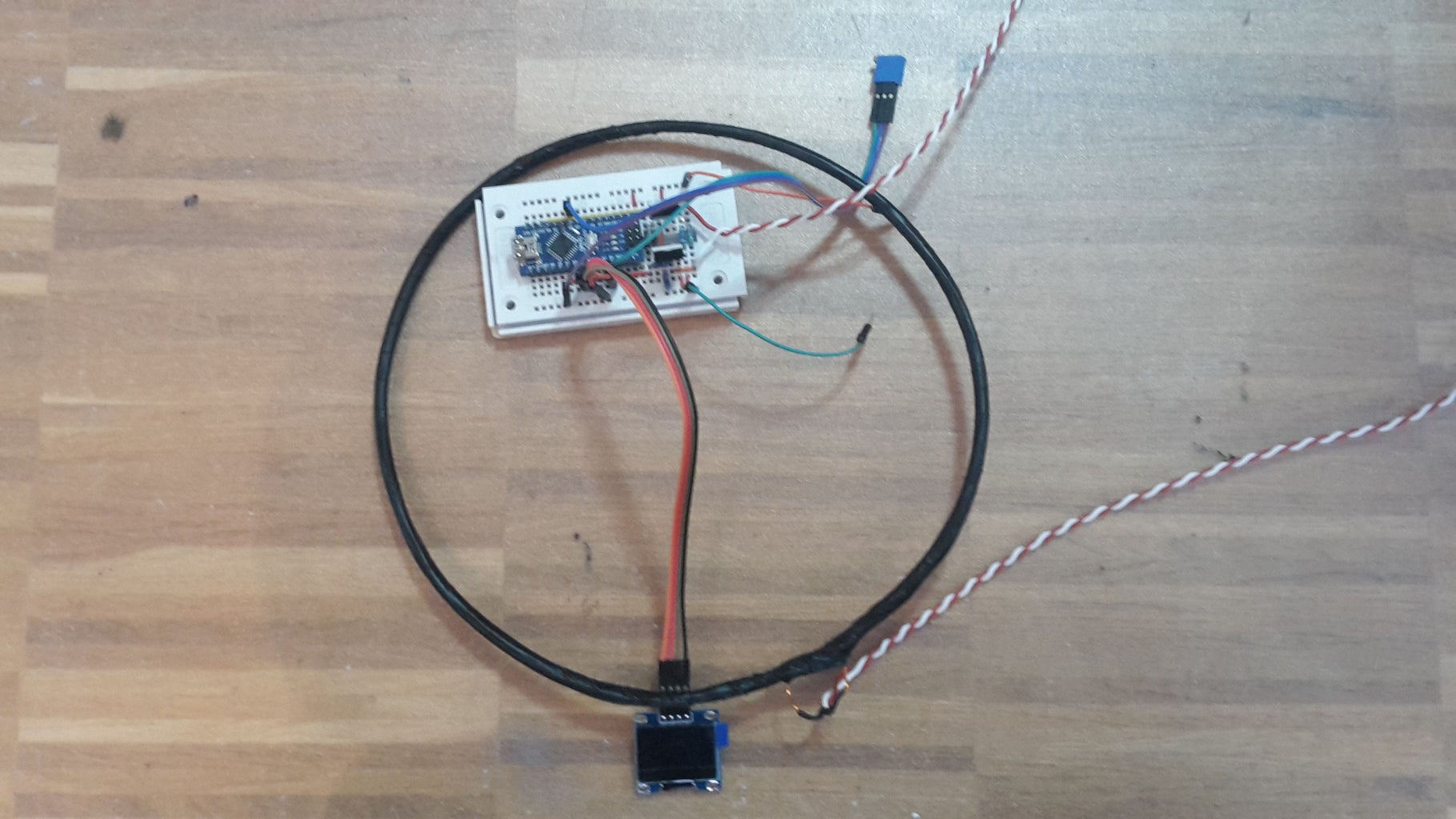
Building the detector is quite easy. This can be done either on a breadboard (sticking to the original circuit) or by soldering the parts on a PCB.
The D13 LED on the Arduino Nano board is used as an indication for metal
Unsing a breadboard is the fastest way to the working detector. Quite some wiring is needed, still this can be done an a small breadboard. In the pictures this is shown in 3 steps as the Arduino and the MOSFETs are hiding some of the wires. When testing I disconnected the diodes somehow without noticing at first. This had no negative effect on the behavior of the detector. In the PCB version of the circuit I left them out completely.
Not shown on the pictures are the connections to a 0.96 OLED display. This display is connected:
Vcc – 5V (at the Arduino pin, not the supply voltage!!!)
GND – GND
SCL – A5
SDA – A4
This OLED Display is needed to calibrate the detector initially. This is done by setting the right voltage at PIN6 of the Arduino. This voltage should be around 0.04V. The display helps to set the right voltage.
The breadboard version works pretty well, although probably not suited for going into the wild.
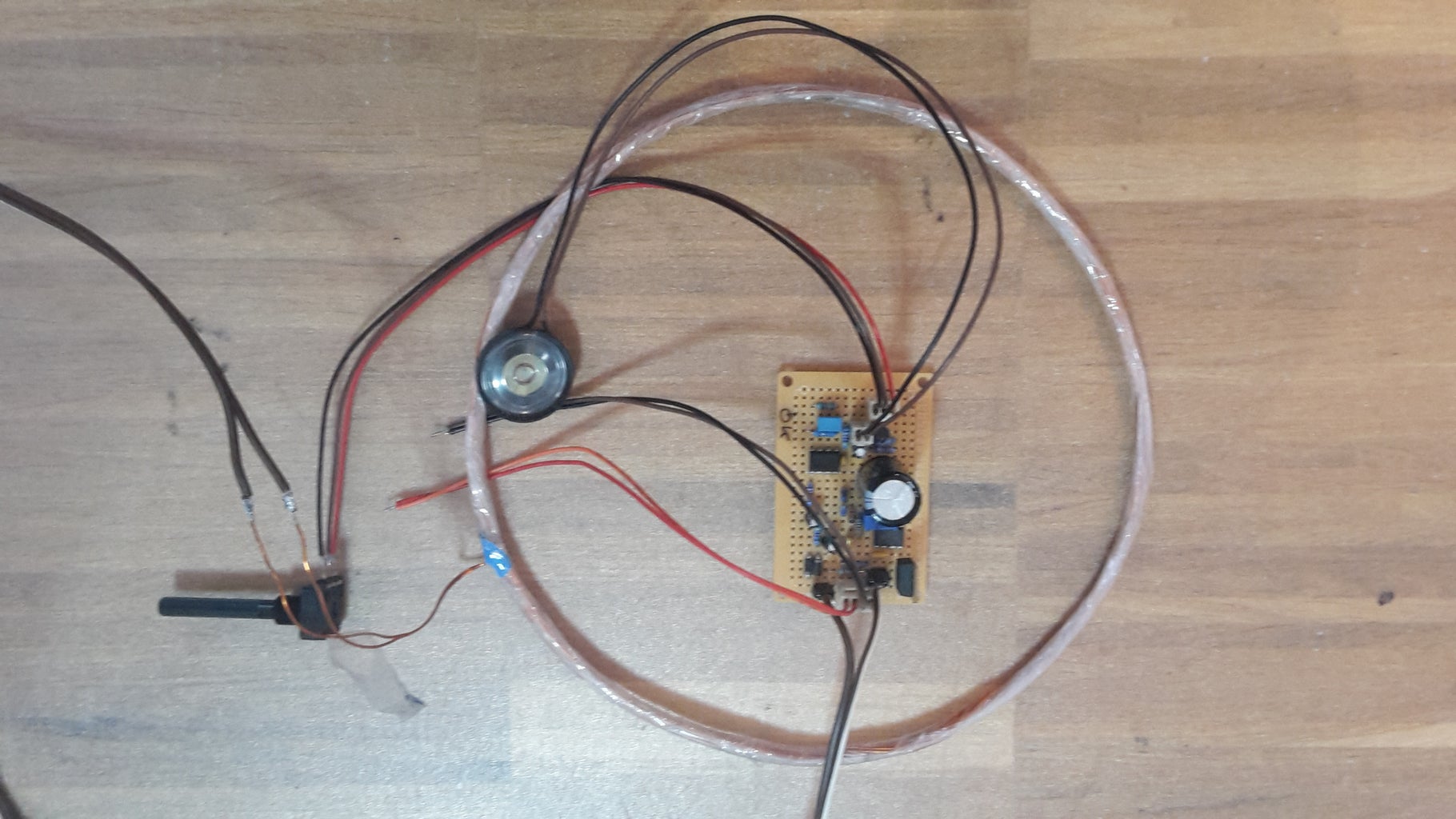
Step 3: Going PCB


As for soldering I do not really like double sided high-tech PCB, so I modified the circuit to fit on a on sided PCB.
Following modifications were made:
1. the diodes were left out.
2. the gates of the MOSFETs got a resistor of 10 Ohm
3. the supply voltage for the voltage-divider at D6 is given by a HIGH level signal at D8
4. driver pin for the MOSFETs was changed.
This way a single sided PCB could be created which can be soldered on universal PCBs. Using this circuit you will having a working PI detector with only 8-10 external components (depending if the OLED display and/or a speaker is used).
Step 4: Setting Up and Using the Detector


If the detector is build properly and the program is written to the Arduino, the easiest (if not the only) way of setting the unit up is to use an OLED display. The display is attached to 5V, GND, A4, A5. The display should show „calibrating“ after the unit is powered up. After some seconds it should say „calibration done“ and three numbers should be shown on the display.
The first number is the „reference value“ identified during calibration. The second value is the last measured value and the third value a a mean-value of the last 32 measurements.
These three values should be more or less the same (in my test-cases under 1000). The middle value should be more or less stable.
To start the initial set up, there should be no metal near to the coil.
Now the voltage divider (trim potentiometer) should be trimmed so that the lower two values should be set to a maximum while still giving stable reading. There is a critical setting, where the middle value starts giving weird readings. Turn back the trimmer to obtain stable values again.
It might happen, that the display freezes. Just press the reset button and start over.
For my setup (coil: 18 turns @ 20cm) the stable value is around 630-650. Once set, press the reset button, the unit re-calibrates and all tree values should be in a same range again. If metal is now brought to coil, the LED on the Arduino-Board (D13) should light up. An attached speaker gives some clicking noises (there some room for improvement in the programming there).
To prevent high expectations:
The detector does detect some stuff, but it stays a very simple and limited detector.
To give an impression of the capabilities, a did some reference detections with different other detectors. Looking at the results, it is still quite impressive for a detector with only 8 external parts but not matching professional detectors.
Looking at the circuit and the program, there is a lot of room for improvement. The values of the resistors were found by experience, the pulse time of 250ms was chosen randomly, the coil parameters as well. If you have ideas for improvements, I would be more than happy to discuss them.
Have fun!
Attachments

Step 5: Update1: Using a 16x2 LCD


Improvements
During further testing I realized that the library for the I2C OLED Display was using up considerable time. So I decided to use a 16x2 display with a I2C converter instead.
So I adopted the program to the LCD display adding some useful features. The first line of the display now shows the signal strength of a possible indication. The second line now shows two values. The fist indicated the current signal deviation compared to the calibration value. This value should be "0". If this value is constantly negative or positive, the detector should be re calibrated by pressing the reset button. Positive values indicate metal near to the coil.
The second value shows the actual delay value of the decay curve. This value is normally not that interesting, but is needed to the initial setup of the detector.
The program now allows for multiple pulse durations in a sequence (means of experimenting / improving the performance). I did not achieve any break through. So default is set to one pulse duration.
Initial Setup of the Detector
When setting up the detector, the second value of the second line is relevant (the first one can be ignored). Initially the value can be "unstable" (see picture). Turn the trim resistor until the value get to a stable reading. Then turn it to increase the value to a maximum stable value. Press the reset button to recalibrate and the detector is ready for use.
I got the impression that by setting the maximum stable value, I lost sensitivity for non-iron metals. So it might be worth some experimenting of the settings to have a good sensitivity for non-iron stuff.
Coils
I build 3 coils for further testing
1 -> 18 turns @ 200mm
2 -> 25 turns @ 100mm
3 -> 48 turns @ 100mm
Interestingly all coils worked pretty well, with almost the same performance (20ct coin at 40-50mm in air). This might be a quite subjective observation.
