

Introduction: Arduino Basic PC With TV Output


In this Instructables I will show how to build a retro 8-bit computer running BASIC, by means of two Arduino and few other components.
You can input the variables and the BASIC program with a PS2 keyboard, and the output is shown on a monitor with a text 47 columns x 29 rows of 8x8 pixels characters (B&W), a resolution similar or better than the Commodore 64, equal to 40 x 25 characters.
You can see it in action in the upper video.
The program can then be saved on the Arduino EEPROM, and you can still control the I/O pins directly via Basic dedicated commands.
One Arduino is the "master", and it runs Tiny Basic Plus, a C implementation of Tiny Basic, with a focus on support for Arduino. It also control a PS2 keyboard. The output is then sent via the serial port to the second Arduino which generates the video output thanks to the awsome MRETV library.
The idea to use one or more Arduino to create an old style PC running a dialect of Basic is not new, but so far there where some strong limitations in the output resolution. In some projects available on the net, people used LCD displays, while in others, to allow the use of monitors, it has been used the TVout library, which has a much lower resolution. Furthermore in many of these projects special shields or hardware has to be build.
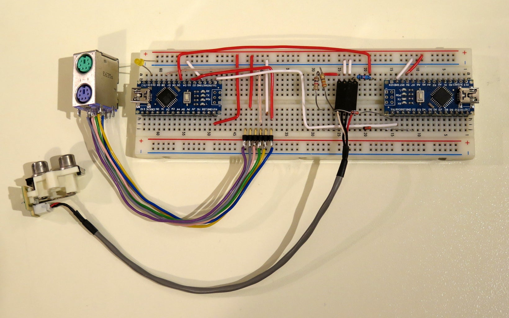
Here you need just two Arduino, a couple of diodes, few resistors and the connector for the PS2 keyboard and the monitor, as shown in the above picture.
Step 1: Build the Arduino Master With TinyBasic and PS2 Keyboard
TinyBasic Plus and MRETV work for elder - and different - Arduino IDE.
First download IDE 1.6.4 from the Arduino official web page. If you have a newer versions on your PC, the best is to download it in .zip format and uncompress them on your PC. Click this link to download the Windows version.
You need then the PS2keyboard library. You can find it at the bottom of this page. Just uncompress it and copy the PS2keyboard folder in: arduino-1.6.4\libraries
Finally, in this page, download the file: TinyBasicPlus_PS2.ino, uncompress and upload it on your Arduino.
This is a variation of the standard TinyBasic Plus where i have added the PS2 library and modified the code to accept the viariable from it.
More details on TiniBasic Plus and tutorials can be found at this link.
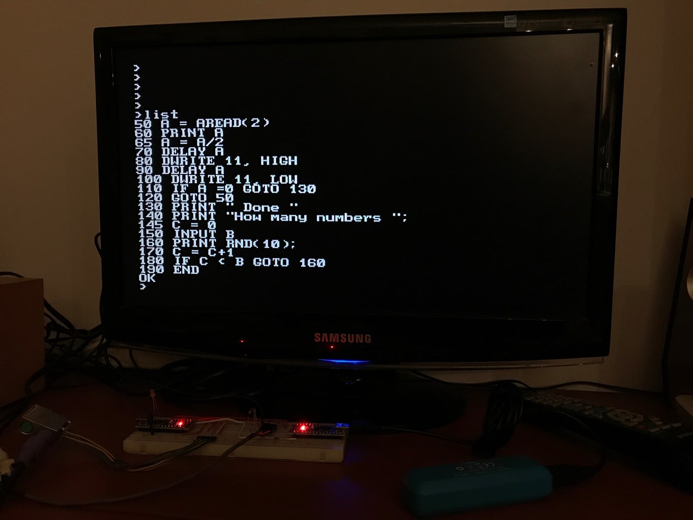
If there are no problems, and compatibility issues, Tiny Basic is already running. You can test it trough a serial monitor in your PC. For this purpose I use PuTTY, but many other programs are available.
You have to set the correct COM port (it is the same you find in the Arduino IDE) and baud rate = 2400
Here you can already test some program in Basic just by typing them with your PC keyboard (NB later on I will show how to connect the PS2 keyboard directly to the Arduino).
Try for instance:
10 PRINT "Hello, World!"
20 GOTO 10
RUN
You can then stop the infinite loop just by typing ctrl+c. Note taht this combination will not work for the PS2 keyboard.
In the next step I will show how to connect the PS2 keyboard to Arduino.

Step 2: Connect the PS2 Keyboard to the Master Arduino

I got all the informations and library from this Instructable.
Essentially you need to connect the folowing four pins:
- keyboard Data to Arduino pin 8,
- keyboard IRQ (clock) to Arduino pin 3;
- of course you need to connenct GND and +5V as well.
I got an old PS2 female connector from a broken PC motherboard.You can simply unsold it with a heat gun.
In the picture shown in this step, you can find the function of the needed pins of the PS2 connector.
Step 3: Upload the MRETV Library on the Second Arduino and Put Everything Together

The key point of this project is the existance of the awesome MRETV library. There is a dedicated Instructable where it is described in details.
It uses only two resistors and two diodes to generate full screen video, with a text resolution of 47 x 29 of 8x8 characters. As it says in the introduction, "video generation has been done before, but not like this. FULL DUPLEX serial still available while generating video". This allow to get the data from the "master" Arduino and show them on the monitor. In practise this second "slave" Arduino is used as a graphic interface!
Since MRETV works for IDE 1.6.6, download it from the Arduino official web page. Again, the best is to download it in .zip format and uncompress them on your PC. Click this link to download the Windows version.
Download then the MRETV library from this link.
Uncompress it and save the folder "MRETV" in: arduino-1.6.6\libraries
Finally download TVtext_slave.rar at the bottom of this page, uncompress it and upload in your Arduino slave.
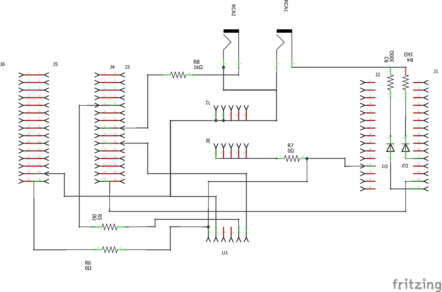
If there are no error message, you can connect the RCA connector. You need the two diodes and the resistors of 1 kOhm and 300 Ohm, as shown in the schematic in this page.
At this point you can connect everything together.
The complete list of materials is:
- two Arduino Uno Rev. 3 or two Arduino Nano 3.x (ATmega328)
- two resistors 1 kOhm
- one resistor 300 Ohm
- two diodes 1n4148 (x2) or similar silicon switching diode
- two RCA plug female (one for video, one - facultative - for audio)
- a PS2 female connector
- a breadboard and wires
The master Arduino sends the data to the slave trough the orange cable, i.e. master pin 1 (Tx) to slave pin 2 (Rx). If you need to re-upload some code, you should disconnect this cable first.
Connect then the slave arduino to a 5V power supply, the RCA cable to the TV and the keyboard to the PS2, and you should now see the code to your TV!
The functions of this Basic dialect are described in details in its homepage (see link in step 2). With the commands "esave" and "eload" you can save one Basic program in the EEPROM. This program is run by default each time you reset the master Arduino. To delete it you can use the command "eformat".
One of the most important features of this program is that you can still drive the master Arduino I/O with dedicated Basic commands, such as
- DWRITE pin,value - set pin with a value (HIGH,HI,LOW,LO)
- AWRITE pin,value - set pin with analog value (pwm) 0..255
- DREAD( pin ) - get the value of the pin
- AREAD( analogPin ) - get the value of the analog pin
Thus you can write a program in Basic that drives some hardware, save it in the EEPROM and then running it automatically just resetting the Arduino.
Attachments
Step 4: Optional: Using a PCB
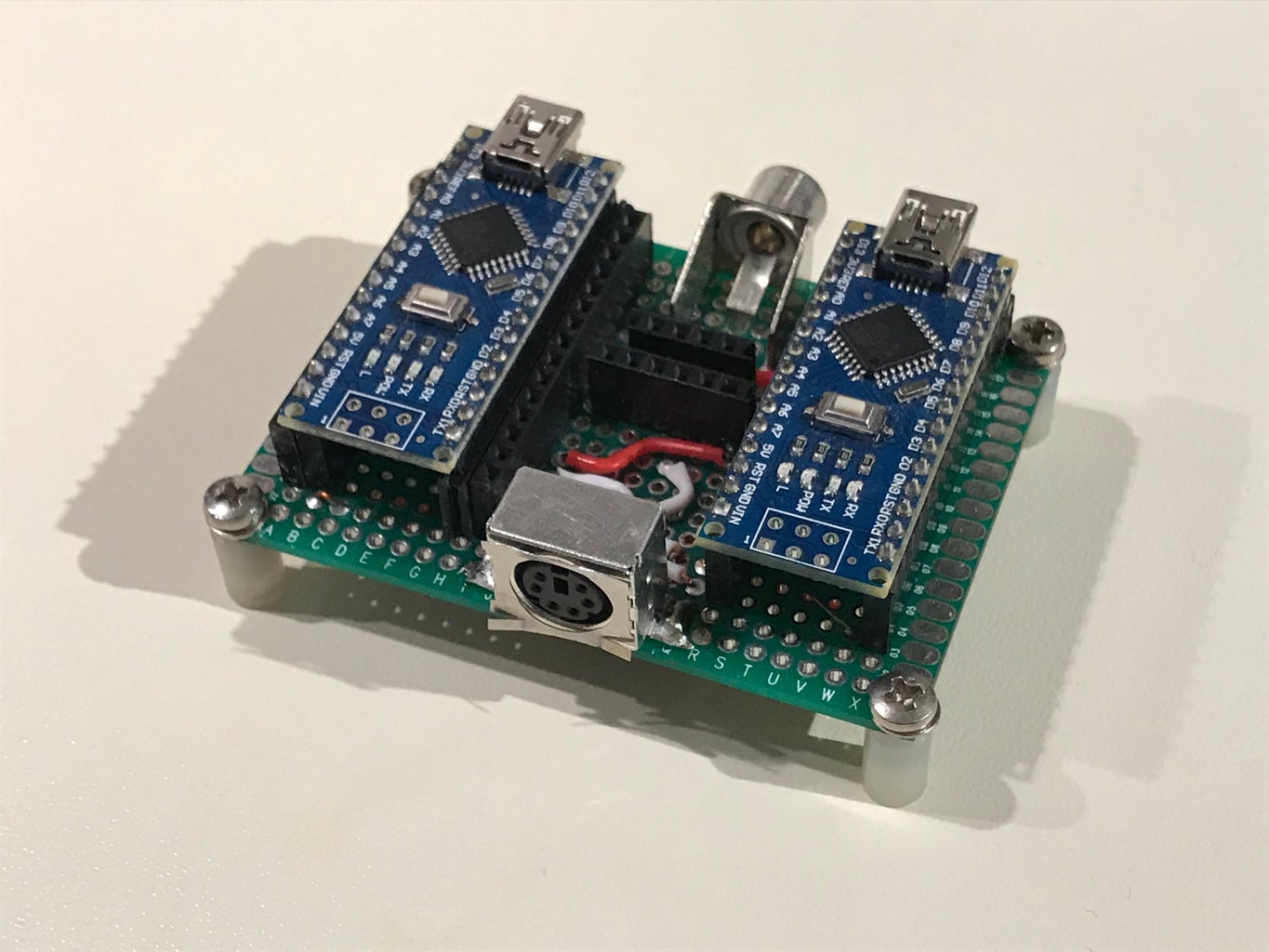

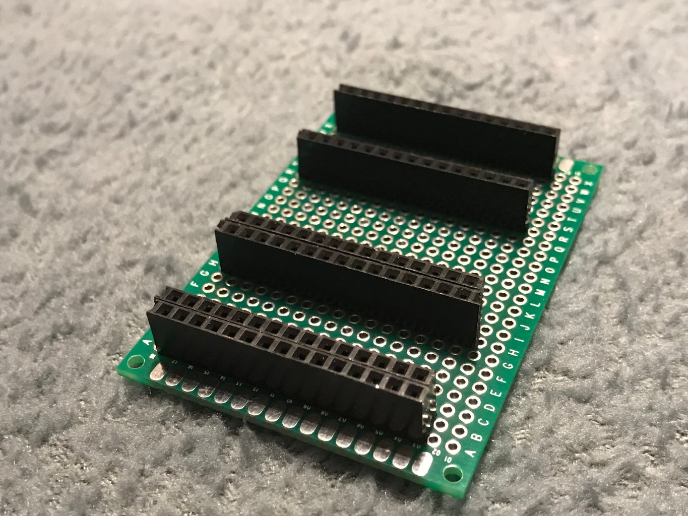
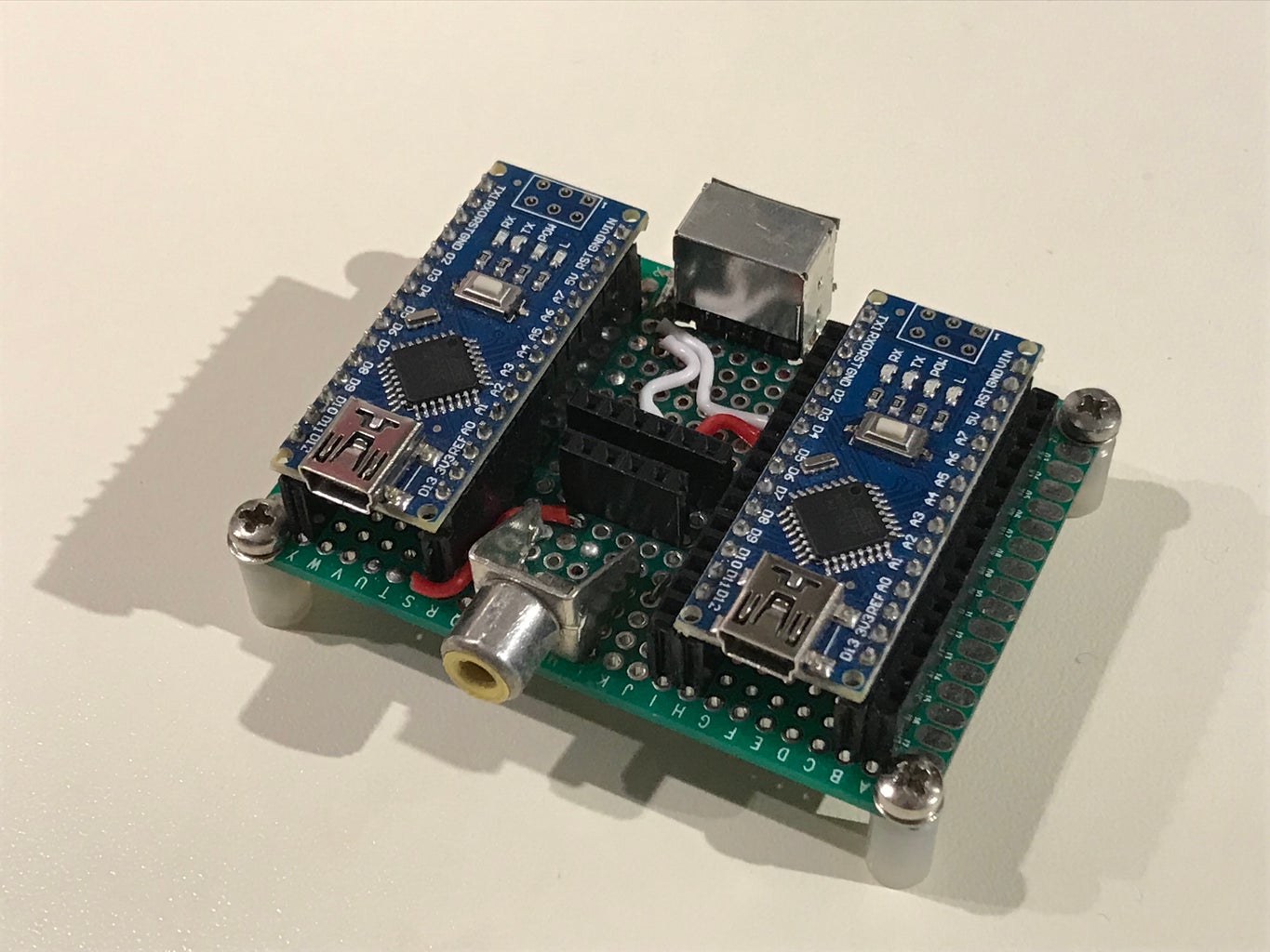
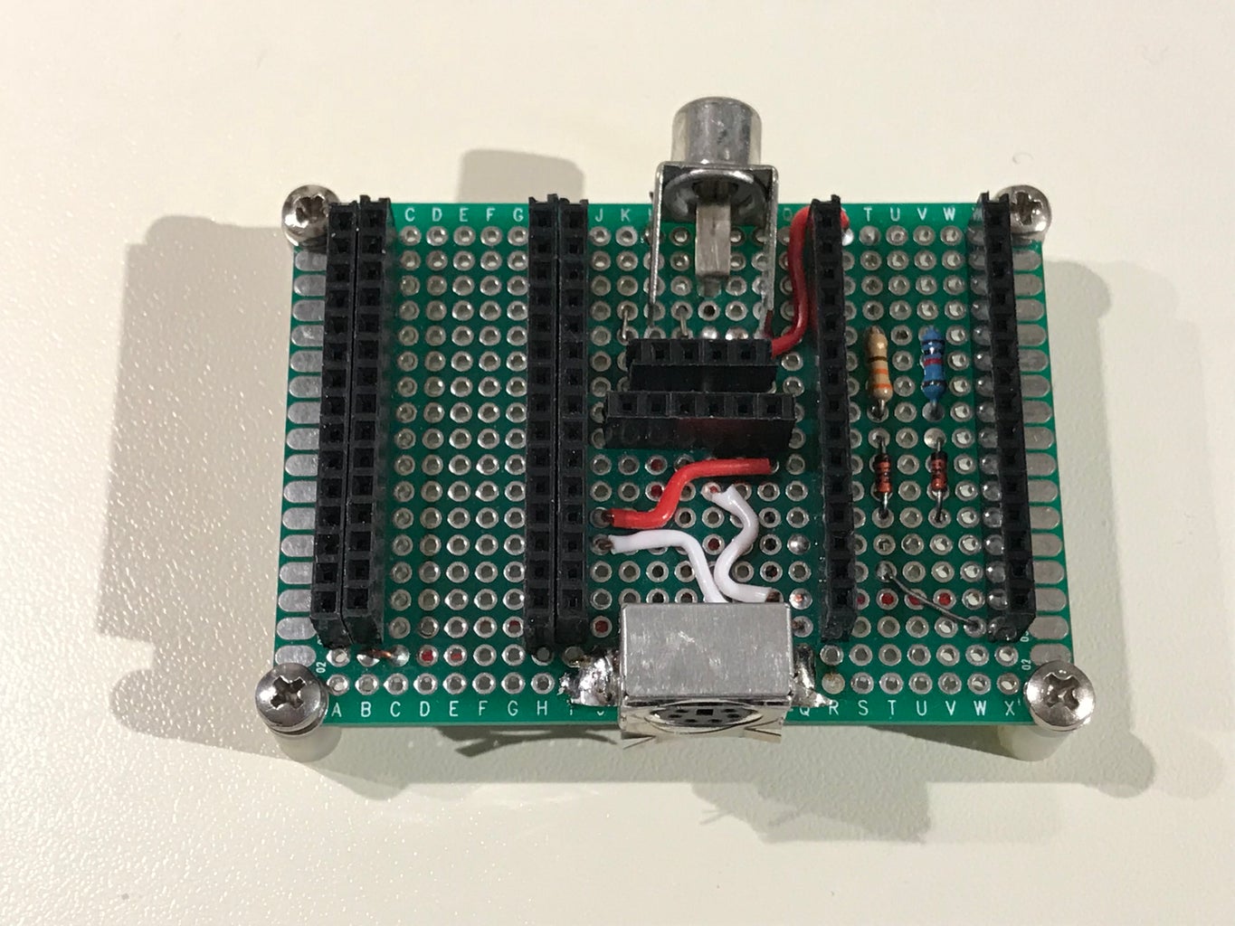
You can also build this Basic PC using a small PCB. You can take inspiration from the pictures in this step or you can even print your board.
You can use two female header strips with 15 holes for the video output Arduino, while for the master I suggest to use four strips. In this way you can use the external ones to insert the contacts of your project componets.
I also added in the center to leftover strips, one conncted to 5 V and the other for GND.
Finally, in the .rar file, you can find the masks to etch a coppered board.
Attachments
Step 5: Final Comments and Acknowledgments
This project could not have been done without the MRETV library. Thus my main acknowledgment goes to his author, which uses the acronym Mr E.
Many thanks also to the authors of TinyBasic Plus:
- Tiny Basic 68k - Gordon Brandly
- Arduino Basic / Tiny Basic C - Michael Field
- Tiny Basic Plus - Scott Lawrence
Thanks also to "djsadeepa", the author of the Instructable for the connection of the PS2 keyboard.
To all the people interested in this project: it is easier to build that it may seem at the first sight. My main problems have been with the Arduino IDE compatibilities. If you have troubles, do not hesitate to ask suggestions in the comments.
If you succeed, please write a comment too or share a picture of the device you build.
