

Introduction: Arduino Controlled Tiny FM Radio


Today, thanks to the continuously growing system integration level of the chips, the making of high quality electronic devices, becomes easy as children play. Another factor helping this is the wide spread of different open source microcontroller development platforms, with plenty of created by electronic enthusiasts libraries, available for free download in Internet. Years ago, to make a nice FM receiver, a lot of experience was required. Such circuit needed few resonant circuits, for which tuning a special equipment was required. Now, when the implementation of complicated digital on chip filters is standard routine, the FM radio circuits become more and more simple - only one chip and few supporting devices perform the whole task.
This FM radio is based on the RDA FM chip RDA5807M. This chip can be found in ebay, aliexpress. banggood and other sites for electronics components. Normally it is sold directly as FM radio module like this on the picture. These modules are pin compatible with the widely spread TEA5767 (Philips) modules. A radio project based on TEA5767 chip can be found here. Both chips use I2C communication with the microcontroller, which sets the different internal registers of the chips, and in this way controls the FM radio receiver chip. The advantages of the RDA5807M chip compared with TEA5767 are following:
- It requires less external components
- It has embedded audio power amplifier, which can be loaded with 32 Ohm speakers.
- It has bass boosting function
Its disadvantage is is the narrower power supply range - the maximum supply, which can be used is 3.6 V - when supplied by Arduino will require 3.3 V voltage regulator.
The datasheet of the RDA5807M is added to the instructable.
Attachments

Step 1: Design Versions


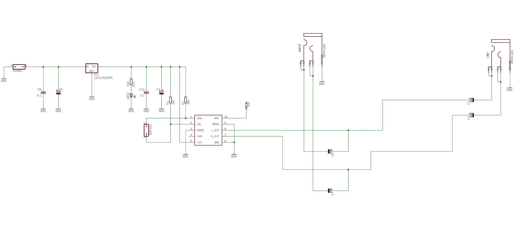
The schematic of the radio is based on the RDA5807M module. The PCB is done in very flexible way - different versions of the radio can be done by omitting some of the devices and bridging some of their PCB contacts.
The possible variants are:
- Simple FM radio - it has only one audio output and uses the internal audio amplifier
- FM radio with two outputs - same as the first, but it has two headphone outputs - one can be used as main, the second as monitoring
- Active audio mixer - mixes the audio signal of the FM radio with another coming from external source. As active mixer I use the TI headphone amplifier LM4880. The volume of the RDA5907M chip is controlled by the microcontroller and the volume of the external audio source by its own.
Normally all these versions work on 5V - A voltage regulator is used for their supply. (I used AMS1117-3.3 in SOT-223 package), but if the microcntroller works on main supply 3,3V (as Arduino DUE), this regulator can be also omitted for the all three versions described above.
How the different versions can be implemented I will explain further.
Step 2: PCB Design

At this step I attach the gerber files for the FM radio PCB.
These are done according the design rules of PCBway. This is Chinese PCB manufacturing company, which works very fast and with high quality. The prices are in contrary very low. Additionally you can chose the PCB color without price increase. To produce and deliver the PCB's them take only ten days. In addition I received 11 instead the 10 boards, which I ordered :-)
Attachments

Step 3: Design Version 3.3V
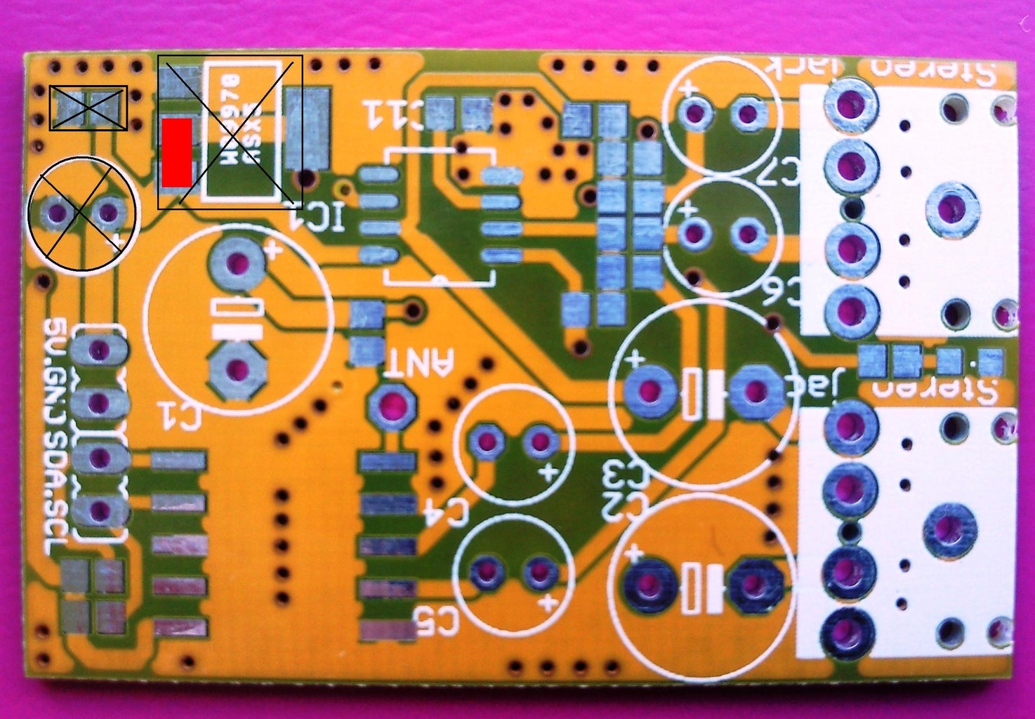

The pictures show which devices should be removed when you want to use the radio at 3.3V
On all pictures for the different versions the red lines (rectangles) show the solder (wire) bridges which have to be done and the black figures with black crossing lines mark which devices shall be not soldered.
Step 4: Simple FM Radio Version


Only one headphone jack is soldered, the LM4880 chip is omitted, the 20 KOhm resistors are bridged.
When working on 3.3 V, the changes done in the previous step are also performed.
Step 5: Version With Two Audio Outputs

How to implement that is shown on the pictures.
Step 6: Mixer Version


All devices soldered. Can be implemented also as 3.3 V in the way described before.
Step 7: Arduino Time

There is a nice FM radio library, which supports few different chips. It is available thanks to Matthias Hertel,
In the library can be found example for used FM chip. The connections with the Arduino are described in the sketch.
The example works with one fixed frequency (83.90 Mhz) - the only thing you should change if you want to hear music. Simply put there the frequency your favorite local FM station.
And do not forget to solder some short (30 -60 cm) isolated cable as antenna. :-)

![Tim's Mechanical Spider Leg [LU9685-20CU]](https://content.instructables.com/FFB/5R4I/LVKZ6G6R/FFB5R4ILVKZ6G6R.png?auto=webp&crop=1.2%3A1&frame=1&width=306)


