

Introduction: Arduino Controlled Versatile Timer/controller


This is a nice and simple versatile on/off timer built around atmel microcontroller Atmega 328 chip.
As the name suggests, it is very versatile timer with N number of applications you can think of.
It can be used to,
- Switching lights in your house on and off (to deter thieves) when you are away
- Controlling your garden lights,
Switching your Air Conditioning on and off Or Room heater On/Off
It can also be used to control the temperature of electric ovens, irons, barbeque or even your soldering iron...
I am using it to control my humidifier in the room and the barbeque temperature in the garden.
This circuit does not contain any temperature sensor but still it does the work of maintaining a fairly constant temperature of electrically operated heaters/coolers by switching them on and off at regular intervals which is of course programmable by the individual user.
Once the system is on and programmed and started.. it continuously shows the time remaining (in seconds) in current mode, updated every second.
Max Delay : 12 Hours
Min Delay : 1 second
The timer operates in 3 modes
1) INITIAL -- This is the time for which the relay will be in ON state when you run the timer first time.
2) OFF -- This is the time for which the relay will be in OFF state.
3) ON -- This is the time for which the relay will be in ON state
so the relay always cycles as following sequence
INITIAL --> OFF --> ON --> OFF --> ON --> OFF --> ON --> . . . . . Indefinitely
Are you thinking where is this INITIAL mode useful??
In case of using it for Barbeque ..
When you switch the barbeque grill on.. it does not heat up immediately.. Mine takes around 4 minutes to heat up to full. so I set INITAL to 4 minutes and OFF to 40 Sec ad ON to 15 Sec to get a controlled heat..
PROS: There are no up and down and Plus and Minus buttons as I have tried to keep it very simple to operate. There is only one white knob(Rotary Encoder) on the top of the instrument which does the all work for me.
CONS: I don't see any.. you tell me ;) I am all ears...
What will you need ?
Here you go...
A)The list of the materials/tools needed is as follows:
wooden sheets 2mm thick 12x12 inches -- 2 numbers, Hack saw blade, a ruler, Drilling machine with 3mm , 5mm bits, a pencil, eraser, sand papers (one fine and one medium grit), P.C.B., 25w soldering iron, soldering wire, wire cutter, a plyer, glue, glue stick and gun
B) Components needed for making PCB:
A copper clad, Ferric chloride powder, PCB drill with drill bits 0.8mm and 1mm, a glossy photo paper, monochrome laser printer, a pair of hand gloves, soap water, scrubber
C) Electronic components needed for making circuit:
IC Atmega 328p - 1 no
IC LM7805 - 1 no
Ic Base 28pin - 1 no
Diodes 1N4001 - 3 nos
Resistors 10k, 2.2k all quarter watt - 1 each
Capacitors 1000/35v, 1000/25v - 1 no
Ceramic disk capacitor 22pf - 2 no
Ceramic disk 0.1uf - 1 no
Crystal 16MHz -1no
Rotary Encoder (with integrated push switch) - 1 no
5pin PCB connector male & female - 1 no
40 pin break-away header(Male) - 1 no
Solid state relay rated@ 240VAC 20Amps - 1no
16x2 LCD display module(Oriole) - 1no
Transformer 9-0-9/500mA - 1no
Copper clad (approx. 4x2 inches) - 1 no
Step 1: PCB Layout

Making PCB for the circuit is the first step. I am not going to teach you here about how to make a PCB as you must be knowing it. The PCB layout is attached in the file timer.pcb which is designed using Express PCB software.
Just print the PCB layout on any glossy photo paper using a monochrome laser printer and transfer the layout on to the copper clad using the old trick of hot Iron(used for pressing clothes) and then etch the PCB using Ferric Chloride solution and you are done.

Step 2: Mounting Components on the Board


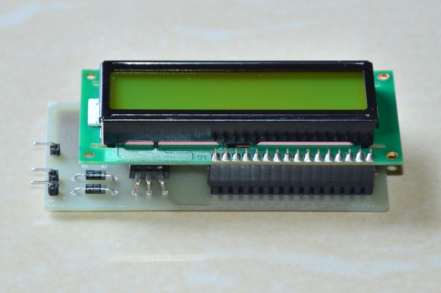
Now solder the components on the PCB . The completed circuit looks like Figure 3
except Atmega IC.. as it needs to be programmed
Step 3: Programming Your Arduino

Connect your arduino board to the computer , load the attached program into the microcontroller using Arduino IDE 1.6
Attachments
Step 4: Device Assembly


After uploading the program into the microcontroller, take out the IC and put it into the IC base of the PCB shown aside. Fit the LCD using the break away header pins as shown in the photo. Notice the angle in which pins are bent for the proper fitting of LCD board over the one we made.
Assemble the complete circuit and test it by powering it ON.
Step 5: Fitting LCD in Case


The photos aside shows.. how to fit the LCD in front panel of the box.
I recommend to not to glue it to the box.
The rectangular slot cut in the wooden sheet should be so perfect that the LCD fits very tightly in it.
Step 6: Box Making


Cut the wooden sheets as per your requirement of size of the box.
I have made the box of size wxdxh , 11x12x8 Cms
Keep some holes in the box for heat dissipation due to SSR and transformer.
Step 7: Electrical Connections Inside Box


See how the complete circuit is fitted inside the box with all the electrical connections secured tightly.
Step 8: Ready to Go...


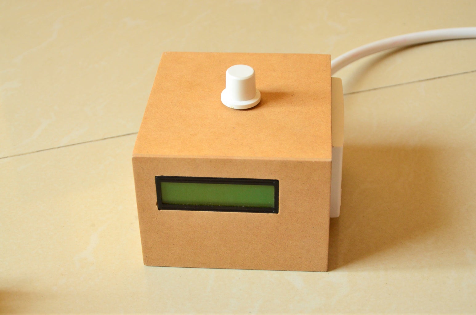

The wooden box is finally brushed thoroughly using a very fine sand paper and then coated with clear varnish spray to give it a good look.
Now the device ready for the operation...
Step 9: Stay Tuned..
Watch this video for detailed operation.... Thanks

Runner Up in the
Microcontroller Contest 2017


