

Introduction: Arduino - Door Event Logger


Ok, so for my first instructable I thought to share something I've just made today.
It's a logger for anything really that consist's of something being on or off ( in the door case, open / closed ).
For this to be applied to a door, the push-button has to be replaced to something like an hall effect sensor ( which I don't have thus the button).
All'right, what i've used:
- Arduino UNO
- DS1307 Real Time Clock
- SD shield ( from this instructable: https://www.instructables.com/id/Arduino-DIY-SD-Card-Logging-Shield )
- 1 led
- 1 push-button
- 220 ohm resistor , 10k resistor and hook-up wire
Step 1: Connecting the Parts
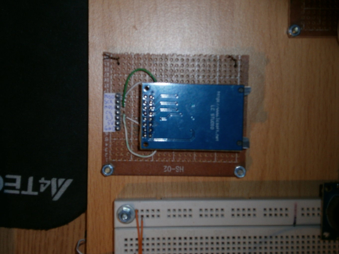
SD card pins:
** MOSI - pin D11
** MISO - pin D12
** SCK - pin D13
** CS - pin D4
+ GND, 5v, 3.3v
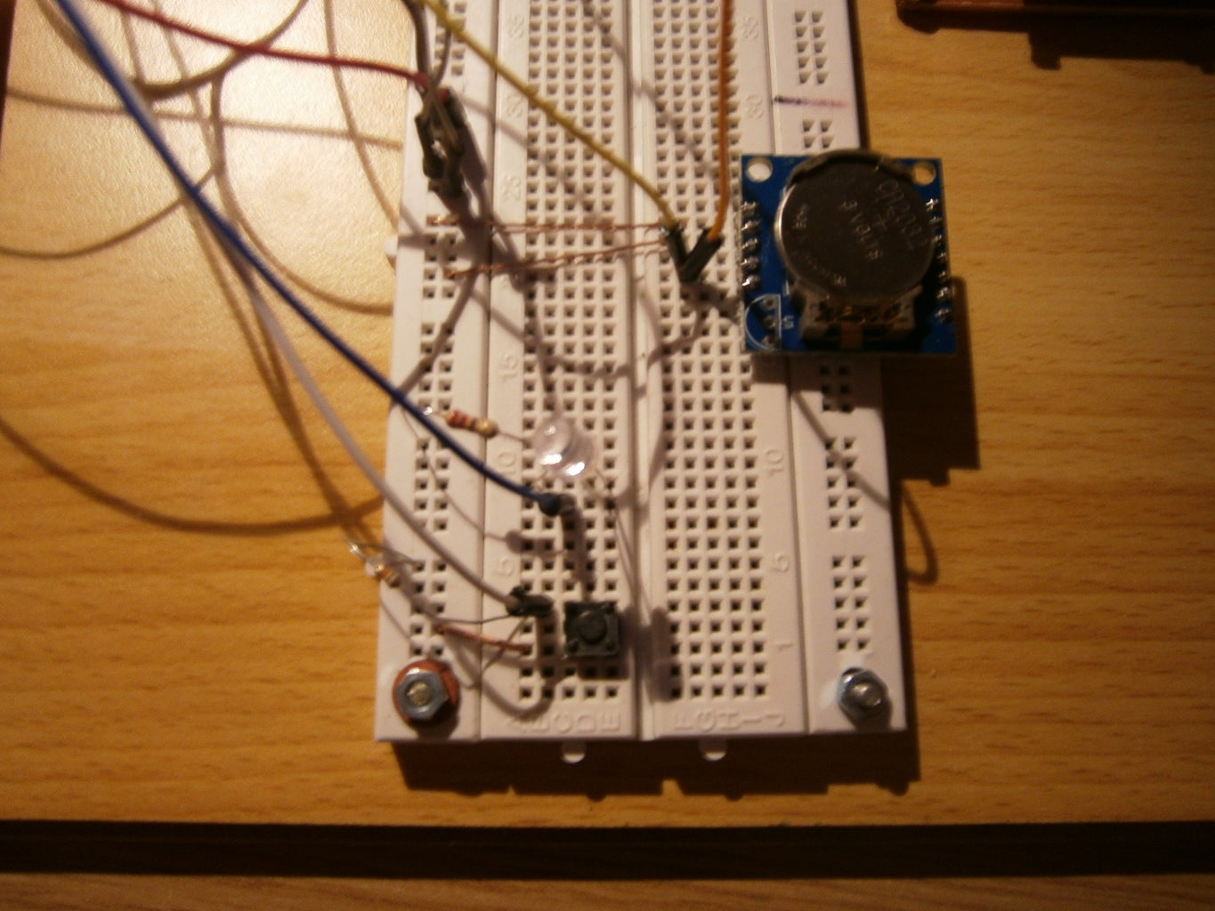
RTC pins:
** SDA - A4
** SCL - A5
** GND - GND
** VCC - 5V
Button + led pins:
** Led's - to 220ohm resistor to GND
** Led's + to D3
** Connect the button to 5V and D2
** Connect 10k resistor from D2 to GND
Step 2: The Code
As for the sketch, download it below.
External library used: adafruit's ds1307 lib ( https://github.com/adafruit/RTClib )
Now, to explain a few things:
variables:
* ok - it stop's the loop if the sd card was not initialized correctly
* first - it log's the first state, and then wait for the state to change before logging it again
functions:
* time() - get the time from RTC and convert it to a string
* SDwrite(int state) - write's on the SD card the time and a message depending on the state it receive's (1 or 0)
* call(int buttonState) - it's used to turn off/on the led and trigger the SDwrite() function
Feel free to contact me for any additional information.
That's it for my first instructable, I'm waiting for feedback.
Attachments

Step 3: UPDATE: Replaced the Button With Hall Effect Sensor

As promised I've replaced the button with a proper sensor for this project: a hall effect sensor.
The sensor I bought is called A3144 (got it off ebay). It has the following pin-configuration: VCC - GND - OUT.
Now to connect it to arduino, just remove the button and do the following.
VCC - to 5V
GND - GND
OUT - D2
* the 10k resistor still remains connected between 5V and D2
The sketch need's a little editing, as the sensor is essentialy an normally open switch and it was previously configured for an normally closed switch.
There are 3 lines of code that need to be modified:
if (buttonState == LOW) to if (buttonState == HIGH)
if (state==LOW) to if (state==HIGH)
if (state==LOW) to if (state==HIGH)
In the picture the sensor is taped to the door frame and the magned is fixed with double-sided tape to the door.
** The hall effect sensor have polarity.
The next stage is to add a remote control switch receiver and transmitter to make the sensor wireless.


