

Introduction: Arduino: Nokia LCD & Sensors


Arduino: Nokia LCD & Sensors
PROBLEM: Making my Arduino, a Temperature-Relative Humidity sensor and a Nokia3310LCD screen work together.
Now, I’m a Lazy Old Geek, so what I wanted was an Arduino kit that would take shields. This Freeduino was the cheapest that I could find at the time.
http://www.seeedstudio.com/depot/freeduino-usb-complete-kit-p-58.html?cPath=79_82
Since I was at Seeedstudio, I also ordered an HSM-20G Temp-RH sensor as it was on closeout and I needed something to try out my Arduino with. Seeedstudio no longer carries these and they’re hard to find. But here’s one site that sells the HSM-20G.
http://www.emartee.com/product/41488/#
My dog, Marcus and I walk every day, so I decided I needed a portable Arduino to display Temp-RH on our walks. My display choice was the Nokia3310LCD shield. Plus it has a cool, little joystick on it.
http://www.nuelectronics.com/estore/index.php?main_page=product_info&cPath=1&products_id=12
So here’s the problems and processes I went through to make it all work.
Parts:
USB Freeduino kit $22
HSM-20G Temp-RH $9 (Closeout)
Nokia3310LCD $14.99
Prices US dollars August 2010
Attachments

Step 1: Connecting the HSM-20G


Here’s the suggested interface circuitry for the HSM-20G. See picture.
Problem 1: The Nokia3310 shield fits on the Freeduino but I didn’t want to connect the HSM-20G to the shield. There’s only three components in the interface but I didn’t have a protoshield or any prototype area on the Nokia3310LCD shield, so I decided to build the interface onto the HSM-20G PCB. This is reasonable as it will always be needed whenever I used the HSM-20G. So I soldered the 10K to the T output and to a ground on the top side of the PCB. See picture.
Caution: This method is not recommended for the inexperienced.
A ground pin can be found by following the Ground (-) on the connector and tracing it on the PCB. The best way to verify that it is ground is to set your DMM to ohms and measure between the (-) pin of the connector and the pin you suspect is ground. It should be shorted (less than an ohm).
Problem 2: Well, I didn’t have a 47uFd capacitor, but I scrounged a 22uFd capacitor from some scrapped printer PCBs. I can tell from the documentation, that all the capacitor does is smooth out the Relative Humidity voltage, so 22uFd should work just fine. So I solder the capacitor to the 100K resistor, then soldered the resistor lead to the H pin on the connector making sure the positive side of the electrolytic capacitor is on this side. Then solder the other side of the resistor to the 10K resistor lead that is soldered to ground. See picture.
Make sure all of the leads aren’t touching other components and there are no solder bridges.
Problem 3: There was no mating connector for the HSM-20G module or a part number. I emailed Seeeduino requesting the brand and part number and of course got no response. But I scrounged through my junk pile and found a connector that worked.
Problem 4: How do I connect it to the Arduino? The preferred way would be to get one of those stackable protoshields and connect the HSM-20G to it. You could also put the interface circuitry on the protoshield. But I didn’t have one.
NOT RECOMMENDED: So I soldered the connector directly to my Freeduino. The (+) goes to a 5V connection. The (-) goes to a ground. The ‘H’ connects to Analog 1 and the ‘T’ to Analog 2.
Caution: When connecting two different sensors or shields, you have to be careful about not overlapping Analog and Digital pins. I started an Excel spreadsheet that has all of my shields and the pins they use. The Nokia3310 shield uses Analog 0 for the joystick so Analog 1 and 2 are available for the HSM-20G.
Here is the site where I found the sample HSM-20G sketch. This person really seems to know what he’s talking about. I verified the formulas with the HSM-20G data sheet. They are very accurate. There are other sensor interfaces on this page, also.
http://sites.google.com/site/measuringstuff/more-sensor-examples#TOC-HSM-20G-Humidity-and-Temperature-Mi
So I was able to run this sample HSM-20G sketch and display temperature and humidity on the PC monitor.
Step 2: Connecting the Nokia3310LCD With Joystick Shield


So, this is easy, just take the shield (see picture). Plug it in. Load the sample sketch and run it. Right?
Problem 5: Well, not so fast. When I first tried it, the LCD screen was dark and hard to read. When I powered it up with an external 9V battery, it was unreadable.
So I emailed nuelectronics with my problem and of course, got no response.
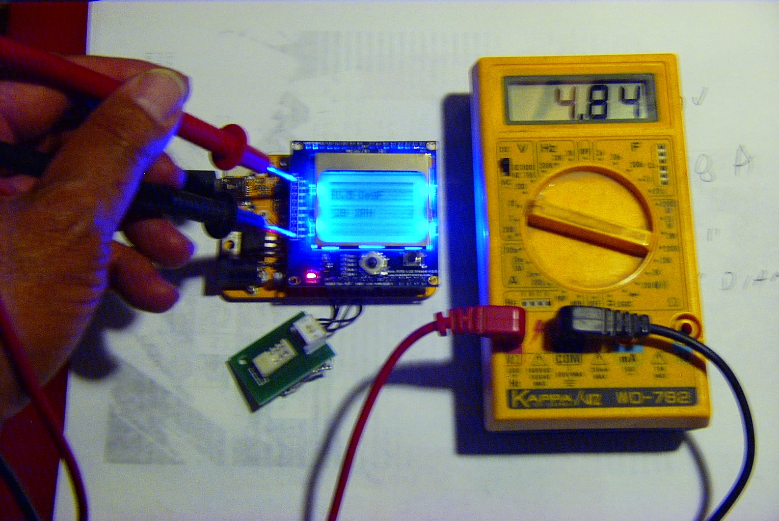
Solution 1?: I wondered why the LCD was better with USB power than with external power. So I measured the 5V. See picture. It was 4.84V. The power was coming from my PC but it was also going through an unpowered USB hub and 4.84V is acceptable. I measured the same place using a 9V battery connected to the 7805 regulator. The voltage was 5.03V, about what I expected.
The tiny LED in my head blinked. I decided the LCD would be more readable if I dropped the ‘5V’ voltage to the Freeduino and the Nokia LCD.
My Freeduino has the typical power supply like the schematic. All I had to do was remove the PWR SEL jumper and replace it with a potentiometer (variable resistor) on pins 1 and 2. (or 2 and 3 if using USB power)
So I scrounged a three pin connector with wires on it and solder two wires to a scrounged 200 ohm potentiometer. For those of you not familiar with potentiometers, they are a resistor with a mechanical wiper that can move from 0 ohms to the maximum (200 in this case). Why 200, well it was the smallest resistance I could find. Potentiometers have three leads. You only need two connections, make sure you solder one to the variable pin. See picture. Then plug it in, see next picture.
So this worked pretty good. I could tweak the potentiometer to get a nice display on the screen. BUT. . .
Step 3: Temperature and Humidity?
So now what’s wrong? I did some thinking (dangerous thing to do for an OLD man). I wonder what changing the 5V does to reading analog voltages. Sure enough, I ran the HSM-20G demo, the temperature and humidity varied with the DC voltage for the Arduino. For a full explanation, I put the Analog to Digital Conversion in another step so most of you can skip it.
Solution 2?: Well, I thought one option was to run the Arduino at 5V and adjust the voltage on the Nokia3310 shield. There didn’t seem any easy way to do that.
Solution 3?: There are ways to set up the Arduino Analog converters so it doesn’t need 5V but this would require a lot of software changes and experimenting, plus I had to consider the joystick was analog also and was already designed for 5V.
Solution 4: While searching around for solutions, I found this website:
http://blog.thiseldo.co.uk/?p=383
‘Andy’ rewrote the libraries for the Nokia3310. I downloaded them and took a look. One of the comments said the initialization of the LCD was updated for a newer version of the LCD that nuelectronics was using. AHA! So I haven’t figured out how Andy found this out from the nuelectronics website, I couldn’t but it would’ve been nice if they’d updated their libraries.
I took the potentiometer out and put the regular jumper back in. So all problems solved, right?
Problem 5: Of course, not. I loaded Andy’s software as best I knew how into the Arduino environment. Then I tried to run his demo program and kept getting compile errors. I took out his sensor stuff since it was different from mine but still kept getting errors.
One of the reasons I decided on the Arduino was so that I didn’t have to delve into .H, .C, .CPP files. I am LAZY and OLD so didn’t want to bother. Well, that didn’t last long. I’m still a GEEK, so with some tweaking to Andy’s files, I managed to get it running. I did my best to decipher the error codes and made changes. I tried to mark all the changes I made with a //MTS. One thing I know isn’t working is big fonts.
I was able to get the demo sensor code into the Nokia code, it is under examples: nokia_Temp_RH.pde
So I zipped up the code that basically works. You should unzip the files right into the Arduino environment libraries.
Mine is \\MICHAEL-PC\Users\Michael\Documents\Arduino\arduino-0018\libraries
So it all works pretty good.
If any of you have had good or bad experiences with the Nokia3310LCD module, I would appreciate a comment. If you have a working library, that would be better yet.
Practical Information: I worked many years in the electronic test and measurement industry. Temperature and humidity vary over distance and time. The sketch takes 10 samples and averages them. Even so, I would guess the temperature is only within +/- 3 degrees and +/- 5% RH. But do you really care? Can you tell the difference between 89 and 92 degrees F. I can’t.
There is one circumstance where temperature could be critical. That is the freezing point of water, 32 degrees F. If this is critical for your application, then you should calibrate your sensor at this point. Probably the easiest way would be to stick the sensor in a baggie and sticking it in a bag of ice. You may have to adjust your formulas to get this temperature more accurate.
By the way, the other ‘fixed’ temperature is the boiling point of water. 212 F. Beware, this is only at sea level. At my altitude (4653 feet) boiling point of water is 203.6 F. Here’s a website calculator to find your boiling point (temperature).
http://www.csgnetwork.com/h2oboilcalc.html
I used Google Earth to find the altitude at my house.
Be very careful if using boiling point as a calibration point.
Here is a suggested method for a one point calibration of Relative Humidity. I am not sure why it should be 75%.
http://exoticpets.about.com/od/herpresources/ss/hygrometer.htm
Step 4: Analog to Digital Conversion


Most of you will want to skip this step.
If you are curious, or having analog problems, or looking to design some analog circuits, this may be helpful.
The ATmega328 has six analog input pins (see pin mapping). I am assuming the chip has only one A/D (analog to digital) converter chip in it. It is called a ten bit converter because it uses ten bits, 210 or 1024. The next drawing is a pretty good representation of how the converter works. The description is pretty technical and not that important for most Arduino users. But look at the analog signal represented by the smoothly curving signal on the top left. The stair step picture on the bottom left is representative of the digital output. You should note that instead of a smoothly curving line like the analog signal, the digital output is very jagged, often called a stair step. For the Arduino, the digital input goes from 0000000000 to 1111111111 which is 1023 steps in decimal.
This digital output doesn’t come out of the ATmega directly. It is only used internally by the software.
For the standard Arduino if you have 5V on the analog pin, the analogRead() will be 1023. Since there are only 1023 different possibilities that means each step is 0.004888 V. What that means is if you have analogRead() of 1023, it might mean 5.000V or 4.996V or somewhere in between. So each stair step means that the actual voltage can be off by 0.004888 V.
Practically speaking: So many of you will say who cares and in most cases you are correct. The accuracy of this reading is dependent on the accuracy of Vcc. If the Arduino is using a 7805 voltage regulator, then the 5V is +/- 1.5% which is 0.075V. The actual voltage could be anywhere for 5.075V to 4.925V which is much greater that the tolerance of a step. Another factor is noise on Vcc and on the analog signal. With a PC USB, the 5V tolerance is usually worse. Mine measured 4.84V.
Practically speaking with the standard Arduino, your Analog accuracy is limited to +/- 1.5% of the 7805 anyway.
NOTE: I am not 100% sure the following is accurate.
Advanced information: The 5V equals 1023 is not always true for the Arduino. The 1023 value is the voltage on the AVcc pin (pin 20 of the ATmega) under most conditions. Usually AVcc is tied to Vcc and is 5V. However, if the sketch contains the function AnalogReference(INTERNAL), then an internal reference of 1.1V (for the ATmega 168 and 328) is used. I am fairly certain what this means is that if you have a 1.1V signal on an analog pin, then the analogRead will be 1023. What this means is each step equals 0.001075V which means you can get more accuracy but it also means your maximum analog input can only be 1.1V. Now AnalogReference() can also be set to EXTERNAL. What this means is the analog reference is equal to the voltage you put on the AREF pin.
WARINING: Be careful if you use EXTERNAL and an external voltage source; this could interfere with and damage the ATmega. If you run a different sketch, that doesn’t have AnalogReference(EXTERNAL) set, then the external voltage reference is going to be fighting the default voltage on AVcc. It’s like connecting two batteries of different voltages together. You have a complete circuit with voltage but zero resistance so lots of current. I think there is a way around this by connecting it through a resistor but am not sure.
The reason I mentioned AVcc and analog reference is that I was setting my Arduino-clone up to use the Nokia LCD. I noticed that LCD worked fairly well when I was using the USB power but it was very dark when I plugged in an Adafruit 9 volt battery adapter. So I grabbed my trusty little DMM and did some troubleshooting. With the USB power, the Vcc and the Aref pin on the ATmega were at 4.84V. With the 9 volt battery connected to the 7805 regulator the two pins were at 5.03V. I also had a temperature sensor attached and further testing verified that the temperature reading varied depending on what the AVcc voltage was.
So if you want to improve upon the accuracy of the ‘standard’ Arduino, there are ways to do it.
If you set AnalogReference(INTERNAL), the ATmega will use 1.1V as a reference, adjust your calculations accordingly.
TIP: Any time you change AnalogReference(), discard the first analog reading as it will be meaningless.
If you set AnalogReference(EXTERNAL), you can provide you own reference, assumed it has a tighter tolerance.
See WARNING above.
TIP: Any time you change AnalogReference(), discard the first analog reading as it will be meaningless.
Those same six analog pins use a different method for output.
D/A (Digital to Analog): The Arduino does not use a D/A (Digital to Analog) converter. Instead it uses, something called:
Pulse Width Modulation (PWM). PWM is not an analog signal. It is a pulsed digital signal. The drawing is from http://arduino.cc/en/Tutorial/PWM.
What the Arduino sends out is a digital signal that pulses off and on at different rates.
Instruction Output
analogWrite(0) 0 volts out
analogWrite(64) see drawing
analogWrite(127) see drawing
analogWrite(255) 5 volts out
The drawing depicts the output over a period of time. As the drawing shows as the analogWrite value goes farther above 0, the width of the positive pulse gets wider. In other words, the time the output stays at 5 volts is longer. Now this is hard to explain but if you think in terms of average voltage when analogWrite is 0 then the average voltage is 0 and when it is 255, then the average voltage is 5V. Now when it is 127, you can see that it is on ½ the time and off ½ the time so the average voltage is 2.5 volts. Now as the value goes larger than 127, you should see that the average voltage goes up.
For those of you who like real world “proof”, here is a way to demonstrate this. A capacitor smooths out DC voltages. That is why you will always see them on Vcc and power supply outputs. Now if you take a capacitor (I’m guessing a 1ufd or maybe .5ufd) from an analog pin to ground. If you write your sketch to set up the analog pin as output and send an analogWrite(127), your DMM should show the voltage at 2.5V. By the way, the mathematics of PWM is beyond me but I know it gets into AC circuitry which is way beyond what this Lazy Old Geek wants to get into.
To put it simply, PWM puts out a signal that simulates an analog signal for most purposes.
TIP: One thing to remember, while the analogRead goes from 0 to 1023, the analogWrite only goes from 0 to 255, a byte by the way.
Non-essential Info: Most adequately designed Arduinos and clones have a 0.01ufd capacitor from Vcc to GND and next to the ATmega chip. The reason is to filter noise from the digital ATmega. When running a sketch, most of the internal circuitry is trying to switch from 0 to 5 volts almost instantly. This produces a lot of noise, a lot of which is high frequency. The capacitor will absorb most of this and smooth it out, just like it did in our little experiment.


