

Introduction: Arduino - Programmable Robotic Arm (Record and Repeat of the Servo Positions)
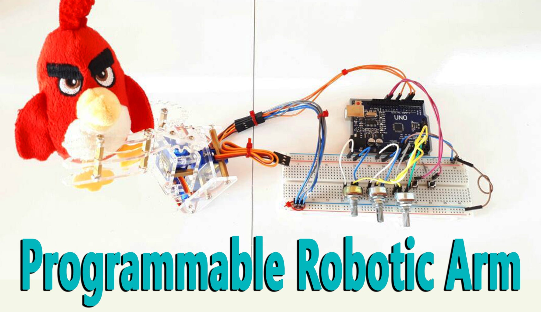


In this project tutorial we will learn how to make programmable robotic arm.
I used 4 DOF simple robot arm for this project, but you can use any robot arm. For example you can use cardboard, hot glue and micro servos for create simple robot arm.
Step 1: Required Hardware

Required Hardware
Arduino Board - https://goo.gl/Rqc5w2
Robot Arm - https://goo.gl/6UZJL6 10K
Potentiometer - https://goo.gl/MPwcEM
Button x2 - https://goo.gl/MPwcEM
10K Resistor x2 - https://goo.gl/MPwcEM
Breadboard - https://goo.gl/MPwcEM
Jump Wires - https://goo.gl/MPwcEM
Power Adapter - https://goo.gl/MPwcEM
Some Promotion Links
Flash Deals -- https://goo.gl/CVqg7P
Mega Stock Clearance -- https://goo.gl/eCbuiP
Arduino Kits -- https://goo.gl/uwr19e
More Budget 3D Printers -- https://goo.gl/uwr19e
Anet A8 3D Printer Promotion -- https://goo.gl/uwr19e
Step 2: Connections


- Arduino VCC and GND connect to VCC and GND of the breadboard
- Power Adapter +V and GND connect to VCC and GND of the breadboard
- Power Adapter GND connect to GND of the Arduino on the breadboard
- Fix the buttons on to breadboard
- Used two buttons. One of the buttons is for recording the servo positions, and the other is for restarting recorded servo positions
- The resistor connect to the one leg of the buttons (Other leg of the resistors connect to GND of the bradboard)
- Other legs of the buttons connect to VCC (+5V) of the breadboard
- Fix the potentiometers on to breadboard
- First button's signal leg connect to digital 12 input of the Arduino
- Second button's signal leg connect to digital 13 input of the Arduino
- Signal (middle) leg of the potentiometers connect to analog A0 - A1 - A2 input of the Arduino respectively
- One leg of the potentiometers connect to GND input of the breadboard
- Other leg of the potentiometers connect to VCC (+5V) input of the breadboard. If you want, you can use other PWM inputs of the Arduino
- The servos power and GND inputs connect to the +V and GND input of the power adapter on the breadboard
Info for the Power
You can use USB via computer for to run of the Arduino board. But you should be use external power for to run of the servos. If you will use external power for this project, make sure the voltage is not more than 6 volts. If there is any jittery, you can use a capacitor for the servos.
Step 3: Source Code


I used 3 pcs micro servos and potentiometer, but you can add more you want.
I also used two buttons. One of the buttons is for recording the servo positions, and the other is for restarting recorded servo positions. The code can be changed, if you add more component so make changes it.
Get the Source Code - https://goo.gl/CKxHF1
Step 4: You Can Subscribe to My YouTube Channel
You can subscribe to the my YouTube channel for more tutorials and projects. Subscribe for support. Thank you.
Go to my YouTube Channel - https://goo.gl/f0RHmR


