

Introduction: Arduino Quartz Clock Controller


This instructable shows how to build an Arduino Quartz Clock Controller and is based around FLORICA TUDOR-NICUSOR's Clock With Alarm, Hygrometer & Thermometer.
This controller will remotely drive, advance/retard & adjust pulse timings of upto 6 Quartz Clocks and is ideal for controlling clocks than are difficult to reach.
Using a simple modification the controller replaces the original quartz clock control board in any 1 seconds drive (the seconds hand steps once per second) quartz clock movement. The built in temperature controlled real time clock provides far greater accuracy than any standard quartz movement.
Further detail on my website here Clock Controller
Video shows controller setup and operation.
Step 1: Functions


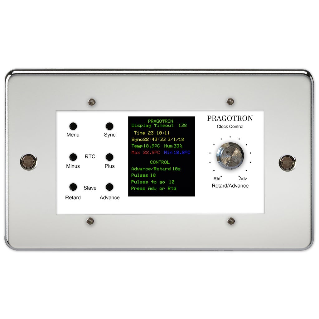
pic 1 & 2 typical setups with controller built into flush mount back box. The panels surrounds are chosen to match existing electrical fittings
pic 3 my clock installation high up in a stairwell, in this example the controller is in another room
The controller has the following features/functions.
Controls a single clock but includes an option to control up to 6 clocks
Clock info displayed on a 1.8" SPI TFT display
TFT display shows RTC time, temperature + daily min/max temperature, humidity, last sync time.
Also displayed are pulse polarity, pulse timing, amount of time to advance/retard, actual & remaining retard & advance pulses.
TFT backlight auto shuts down after 5 min or after advance retard + 5mins Auto shutdown is disabled when in clock setting menus TFT backlight comes on automatically when the Advance/Retard setting knob is moved
Manual time synchronisation to 30 seconds
Remote quartz slave clock setting (advance/retard) from the control panel rotary selector There is a special setting to advance or retard 1 hour for summer/winter changes, including updating the real time clock
Controlled by a DS3231 AT24C32 I2C Precision Real Time Clock Module The DS3231 module has been modified to run off a non rechargeable battery Battery backup by 3 x 1.5v cells to keep the quartz clocks running in case of power loss (the RTC has it's own battery backup as well)
I built this controller to drive my Pragotron PPH410 that has a hi-torque quartz clock movement fitted on import from eastern Europe.
Many Pragotron clocks are imported with their original stepper motors removed and a replacement hi-torque quartz motor fitted. I usually convert these clocks back to their original 1 minute movements but these can be a bit noisy. My PPH410 is mounted on a wall above the stairs the other side of which is a bedroom. The 1 minute stepping of the clock motor would be too noisy at night so I have left the quartz motor in place. This means I would have to climb a ladder over the stairs to access the clock to set the time, change the battery or adjust for summer and winter time. Using this controller means it can all be done remotely from the controller situated in a convenient location.
Step 2: 1.8" SPI TFT Display


pic 1 The controller uses a 18." SPI TFT display to show setting and control information.
The TFT Display contains the following info
Row 1 Name of controller (Pragotron as it's the type of clock it's controlling)
Row 2 Name of controller / version number
Row 3 Displays the Time and also displays the word "Sync" when sync is pressed
Row 4 Temperature & Humidity
Row 5 Max & Min Temperature
Row 6 Motor coil pulse time ON and polarity
Row 7 Amount of time slave clocks will be advanced or retarded if "Advance" or "Retard" buttons are pressed Row 8 Number of pulses to advance or retard and pulse on time in mS
Row 9 Remaining pulses to advance or retard the clock
Row 10/11 Instructions/ Clock Advancing/Retarding info The TFT display is powered by the 5v power supply but the data pins are only rated at 3.3v. I connect a HCF4050BE between the 5v data pins from the Arduino and the 3.3v pins of the TFT display to act as a buffer. Important make sure the HCF4050BE is connected to the 3.3v power pin from the Arduino.
pics 2-4 rear view of the TFT display showing connections
Step 3: Clock Movement Pulse Control


The controller has a 5v power supply and this is fed via preset resistor VR2 adjusted to kick a good kick to the stepper motor without overdriving it.
The pulse duration is controlled by VR3 and is displayed on the TFT is mS. This should be adjusted to the lower setting possible along with VR2 to keep the movement ticking without any missed steps. Make sure that the clock movement will still step with the hands at a quarter to nine as the hands require the most power at this time to lift them up. My test clock ran well on a 40mS pulse and failed at around 10mS. This will vary on the clock motor and hand combination. Make sure the settings work in clock advance mode as well. Pic 1 the clock motor polarity is reversed precisely every second controlled by the RTC with coil A being the opposite of Coil B for the duration set by VR3. Once the time set by VR3 has elapsed both coils are set to 0v.
Looped animation shows the coil polarity and pulse time indicators on the TFT display.
The indicators show the polarity of each coil input and only show when pulsing the coils. The indicators show the polarity reversing on each second change. The display also shows the pulse timings in mS 2 rows down from the polarity indicators. This setting changes as VR3 is adjusted.
pic 3 When the clock is set to advance time an extra pulse is added on the half second effectively doubling the speed of any clocks attached to the controller.
Step 4: Slave Clock Setting & Correction


Slave Clock Setting/Correction
Animation 1
Advancing Slave Time The animated loop shows the actual time on the TFT display is 23:08 & 10 seconds. The slave clock is 10 seconds slow. To correct the slave clock the rotary dial is turned until the "Advance/Retard" time is shown as 10s. The "Advance" button is then pressed and the slave clock receives an extra 10 pulses to correct the time. While advancing the TFT display shows "Advancing Clocks Press Rtd to Cancel" The slave clock is then back in sync 10 seconds later. The TFT display shows the number of pulses and also the number of pulses to go before the slave clock is in sync.
Animation 2
Retarding Slave Time The animated loop shows the actual time on the TFT display is 5:37 & 1 second. The slave clock is 10 seconds fast. To correct the slave clock the rotary dial is turned until the "Advance/Retard" time is shown as 10s. The "Retard" button is then pressed (in this case when the TFT display shows 7 seconds) and the slave clock then stops missing the next 10 pulses to correct the time. While retarding the TFT display shows "Retarding Clocks Press Adv to Cancel" The slave clock is then back in sync 10 seconds later. The TFT display shows the number of pulses to miss and also the number of pulses to go before the slave clock is in sync.
Advance and Retard times In order to advance and retard these clocks either they are stopped to retard or an extra pulse is added on the half second to retard. Any change will take as long as the clock is out to correct. This means if the clock is an hour fast it will take an hour to correct as it will just sit and wait for time to catch up. The same goes if the clock is an hour slow he clock will take an hour to catch up. Unless the clock being controlled is out of reach as my clock is it will be far quicker to change the clock by using the built in hand adjuster. The controller can then be used for fine adjustments.
Step 5: Advance/Retard Selector

The amount the slaves are advanced or retarded is selected by rotating the "Retard/Advance" selector.
As the selector knob is rotated the selected "Advance/Retard" time is shown on the TFT display. The display also shows the number of pulses and number of pulses remaining once the "Advance" or "Retard" buttons have been pressed. The settings advance/retard the slave clock only apart from the Summer Winter setting where the controller RTC is also adjusted once the pulsing has completed.
The table shows the available settings on the Retard/Advance selector control
Step 6: Block Diagram

Circuit Connections
The block diagram shows the connections to the Arduino Nano.
The TFT display has a HCF4050BE IC as a voltage buffer. The TFT display pins are 3.3v while the Nano output pins are at 5v
If only one slave clock is being controlled then the 2nd HCF4050BE IC is not required and the single slave is connected direct to the Arduino.
Step 7: Power & Battery Backup


Power
The controller runs off 5v and is supplied from a 12v power supply unit.
pic 1 The local PSU module soldered to the main board uses a MP1584 miniature power supply to convert the 12v input to the 5v for the clock.
The clock controller draws 36mA with the display on and 14mA with the backlight LED off. This is with the backlight LED set to 30mA.
Battery Backup
Apart from the coin cell in the RTC that stores the time the clock controller has a battery backup to keep the controller and any connected clock working during power failure. The backup battery should last for a week if the display backlight is off. The backup battery comprises of 3 AA Alkaline batteries stored in a battery holder.
The batteries are isolated from the main 5v power in by diode D2. When main power is on the Diode is reverse biased (as the PSU voltage is greater than the battery voltage) and will not conduct. On power fail the diode is forward biased and allows the battery to supply the controller and clocks. D1 isolates the PSU from the batteries. The PSU is adjusted to 5v on the cathode side of D1 and must be greater than the battery voltage measured on the cathode of D2.
The 3 AA batteries are mounted in a plastic case.
Step 8: Construction Front Panel


pic 1 The controller is built into a blank euro socket faceplate.
pic 2 The controller is being fitted to a stud wall so the faceplate is fitted to a 45mm deep box.
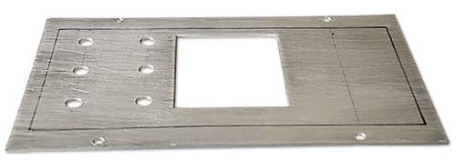
pic 3 & 4 The hole in the faceplate is filled with a panel cut from a sheet of aluminium. Holes are drilled for the switches & control knob and a hole is cut to take the TFT display.
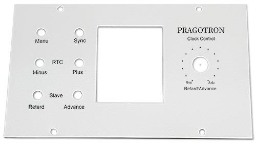
pic 5,6,7 & 8 the aluminium is painted white then Lazertran transfers are drawn up on a CAD program printed and applied to the panel. A couple of coats of clear lacquer seals the transfer in place.
Step 9: Construction Mounting Boards in the Drywall Box


The switch board, TFT display, control knob and RTC are mounted on the front panel see next step.
The mainboard is screwed into a small piece of plywood that is screwed to the bottom of the drywall box from behind. This makes it easy to remove without taking the drywall box out of the wall.
animation 1 shows the sequence of the construction layers of the controller with pics 1-4 showing some of the sequence from the animation.
Note the RTC battery holder in pic 4 de-soldered and re-mounted on the main board as there was not enough space
Step 10: Construction Mounting Boards/modules on the Front Panel


pic 1 shows the back of the faceplate with the plastic euro mount adaptor removed. four holes have been drilled in the faceplate to accept the bolts to hold the new aluminium panel in place.
pic 2 Aluminium panel bolted in place by 4 x M2 bolts and self locking nuts.
pic 3 The 10K pot is fixed to the hole drilled in the aluminium faceplate. The TFT display is hot melt glued in place The switch Vero board is fixed to two of the aluminium faceplate mounting bolts with additional self locking nuts as spacers
pic 4 Rear of faceplate with RTC bolted to the switch Veroboard. The battery holder is de-soldered and mounted on the main Vero board.
pic 5 & 6 Wiring from main Veroboard to control panel and other boards is via Dupont connectors. To keep the wiring neat and to make connection simple I wire connections on the Veroboard to strips of connectors and try to arrange the Nano pins where possible in continuous rows. I then use single Dupont connector joined by black tape to make multiple connector strips. The wiring is then laced together to make cables.
pic 7 shows the Veroboard, wiring harness and front panel.
Step 11: Construction Vero Boards


The controller requires 2 Veroboards, one for the main board and one for the control switches.
pic 2 shows the switch board which has 6 PCB mount micro switches (pic 3) attached.
Main board pic 1
This pic shows the Veroboard without the Nano and PSU module connected.
Main board pic 4
This pic shows the Veroboard with the Nano and PSU module connected.
Main board pic 5
Main Vero Board Option
As I am only controlling 1 clock I have removed the 4050BE IC that drives the other clocks and fitted the battery holder from the RTC in its place. I found with the RTC mounted on the switch Veroboard the battery holder touched the top of the NANO when the case was shut. If you fit the NANO on low profile sockets or solder direct to the board there should be enough clearance without removing the battery holder from the RTC.
Step 12: Construction Completed Box and Panel


pics 1-5 show the completed front panel and drywall box
Step 13: RTC Real Time Clock Modification


DS3231 Real Time Clock Module Modification
RTC Battery holder removal.
pic 1 To make a bit more space in the case I have de-soldered the backup battery holder from the RTC. The battery holder pins can be seen to the right of the diode and just above the SCL label.
pic 2 Battery holder in place on the back of the RTC
pic 3 Once removed the battery holder is soldered on place of IC on the main Vero Board.
Modification of DS3231 AT24C32 I2C Precision Real Time Clock Module to allow use of non rechargeable batteries
pic 4 & 5 My clock uses a DS3231 AT24C32 I2C Precision Real Time Clock Module.
The module comes supplied with a Lithium-Ion rechargeable battery see diagram above. I use a non rechargeable battery so have removed resistor R5 from the module see schematics.
pic 6 Location of R5 on the DS3231 module.
pic 7 R5 resistor removed.
Step 14: Quartz Clock Movement Modification


Quartz Clock Movements
animation 1 Quartz clocks are driven by a Lavet type stepping motor. The motor is driven by reversing the polarity to the drive coil which causes the permanent magnet toothed rotor (in red below) to turn 180°. The toothed rotor will continue to turn in the same direction each time the drive motor polarity is reversed. 2 output pins from the Arduino are used to pulse the drive motor with 1 pin always the opposite to the other.
Quartz Clock Motor Modification
In order to control the quartz clocks 2 wires need to be connected to the drive coil of the clock motor.
Modifying a 12888 Type Seconds Motor
My Pragotron PPH410 was fitted with a 12888 type movement.
To get to the control board most of the gear train has to be removed. Animation 2 shows the placement and order of the gears.
Remove the movement from the clock and carefully pull the hands off the shafts.
The Perspex top cover is then unclipped by prising the two securing lugs apart.
Remove the cogs as shown in animation 2 and put them aside keeping them away from dust.
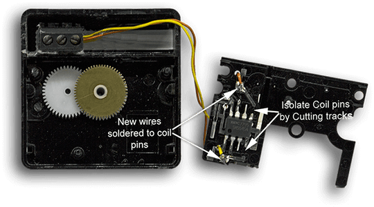
Pull out the plastic coil and circuit board holder then slip the stator pic1 out from the back of the coil pic 2 to release it and the circuit board from the black plastic holder.
The circuit board is attached to the coil pic 3 and the coil needs to be electrically isolated from the rest of the electronics on the board. Pic 4 shows the 2 cuts in the PCB track to isolate the coil.
Solder a wire to each coil terminal and take them out through the battery bay and connect to the Nano or 4050 clock drivers as required.
U.T.S. Quartz Clock Movement Modification
pics 5 to 8 Carefully prise the movement apart and remove the top and bottom case sections.
pic 9 The Quartz PCB and motor section can then be lifted out as 1 part.
Turn the Quartz PCB and motor section over to reveal the solder side of the PCB. Cut one of the tracks to the motor coil to isolate it. Solder wires to each of the coil solder pads and take them out of the clock into the battery bay.
Solder the wires to the "Clk Motor Coil" terminals on the Lavet type stepping motor. Cut tiny slots in the case if required to let the wires pass through then clip the case back together.
All clock movements
pic 10 If you are controlling a single clock then the 2 zener diodes and variable resistor can be located on the main board. If multiple clocks are being controlled then make up a small Veroboard for each clock to hold theses components along with a PCB mount switch so each clock can be turned off when on initial setup.
For multiple clock control the Lavet type stepping motor driver board is "hot melt" glued in place.
There are many different types of drive motors around just follow the process above to convert them.
pics 11,12 & 13 show some different types of clock movements
Step 15: Schematic

Schematic also shows alternative to IC1 HCF4050BE- an 8 way logic level converter.
Also optional extra quartz clock drivers made up of another HCF4050BE. This can drive 6 clocks in total. If single clock drive required leave out IC2 and connect clock to Zener diodes D4 and D3.
Also shown is the optional buffer converter module that can replace IC1.
Step 16: Code
Code
Requires the following libraries
Adafruit_ST7735.h
Adafruit_GFX.h
Wire.h
SPI.h


