

Introduction: Arduino Real Time Clock (DS1307)


This time I will be showing you how to make a module for letting the Arduino find out the time. Although there are many tutorials for the Real Time Clock module I wanted to make my version of this module entirely focused on the step by step soldering. The Instructable will also try to include as much example code as possible so that the reader will get more than the basic knowledge of this module.
This module has the integrated time keeping system using a crystal oscillator. So the timing is accurate with multiple applications. This module also has a battery backup with which the module can keep track of the time even when the Arduino is programmed or turned off. Lets start off with the stuff you will learn and the applications of this module.
Stuff You Will Learn:
- The code required to access the module and get the current time.
- The code for setting the time.
- A simple program with which the user can interact with the module.
Uses of The Project:
- Once you are done with this Instructable you will be able to make your own Digital Clock.
- You can build on the idea and make an Alarm Clock.
- This Module is the timekeeper for many projects like The Propeller Clock, The Nixie Clock, etc.
Components Required:
Component for the Module:
- DS 1307.
- 8-Pin DIP Socket.
- CR 2032 Button Cell.
- Button Battery Holder.
- 4-Pin Connector.
- 10k Resistor 1/4 Watt.
- 32.768kHz Oscillator Crystals.
- Prototype Board.
Additional Components:
When I designed this module I ignored the square wave pin, Since I didn't find it useful in my application but you may add an extra pin if the need arises.
Step 1: About the DS 1307


Introduction:
Apart from the arduino the DS1307 Integrated Circuit is the core of this project since it acts as the timekeeper and tells the arduino when it should leave the appliance on. The DS 1307 is specifically designed for timekeeping, The time is fairly accurate with an error (time drift) of about 1 minute per month. If u want to eliminate this u can go for the DS3234 which has a time drift of only 1 minute per year. For our particular application we can settle for the DS1307 itself.
The beauty of the DS1307 is that it has this backup coin cell. This Coin Cell is commonly the CR2032. This battery is more than enough for the IC since the DS1307 has a fairly low power consumption the backup battery life of the cell is about a minimum of 9 years of usage.
So now that the specs have been discussed lets talk about the communication. The DS 1307 communicates with the arduino using I²C communication. Simply put the chip sends data in decimal form such that each decimal form is 4 bits of binary data also known as Binary Coded Decimal System.
Important Pins:
5V Pin: When this pin is high then the ds1307 sends the data and when it is low it runs on the backup button cell.
GND: This is the ground pin for the module. Both the ground of the battery and the power supply are tied together.
SCL: It is the i2c clock pin - Which communicates with the RTC.
SDA: It is the i2c data pin - Which communicates with the RTC.
So now that the introductions are done lets get to actually making the module. The instructable has steps of the soldering and the places of the components in the board. Hope this method is better to understand than just providing the circuit diagram.
Step 2: Assembly and Soldering - 1


So the module is only 2 x 3 cm in size, which is pretty compact. The module has a wire connector but you can also use a male or female header so that it can be directly plugged into the Arduino. Anyway apart from the square wave pin not soldered the module has all the functional features.
Making The Module:
Step 1:
Cut the prototype board to the size mentioned above and insert the coin cell holder. Then solder the bottom end to hold the cell in its place.
Step 2:
Insert the DIP socket right next to the cell holder but leave space for the crystal oscillator like in the diagram. Solder some pins to hold the socket in place.
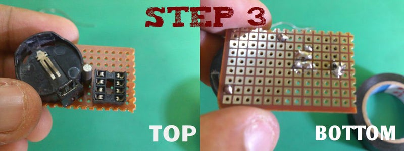
Step 3:
Now insert the crystal Oscillator near the first and second pin of the DIP Socket as shown in the figure. Then solder it as shown.
Note 1:
This note is for showing the colour code for my 4 pin connector for reference, since yours may vary please double check that the proper connections are made.
Note 2:
Now we need to connect the battery terminals using the tracks as shown in the diagram. These connections provide the backup power.
Step 3: Assembly and Soldering - 2


Step 5:
Now insert the power pins coming from the Arduino. The positive pin goes to the eighth pin of the DS 1307. Then the ground is common for the IC and the button cell.
Step 6:
In this step we connect the other two data pins coming from the Arduino as shown in the figure. I'm sorry because I made the module a little small so there was no hole for the 10k resistor. I inserted both the resistor and the wire in the same pin and then soldered.
Step 7:
So after you inserted the wires next we need to insert 10k resistors each into the two pins. The other ends of the two resistors goes to the power pin eight of the DS 1307. Then solder up the wires, a diagram is provided for reference.
Step 8:
Since I use a connector in this module frequent usage will lead to wear and tear of the wires. So i made a joint using the cut of wire from the resistors. First insert the wire into one end and solder it to make it sturdy. Then make a U-bend and pass the wires through this U-bend and tighten the U-bend for a good grip and then solder the other end too to make a joint. The diagram explains the method better than words.
The module is finally finished so insert both the battery and the DS1307 IC into their sockets. The final diagram shows the completed module with all intact.
Step 4: Checking and Setting the Module


Once you are done assembling the module. Connect the module to the Arduino, so that the pins are inserted properly into the Arduino. The program for testing the module is given below. The code constantly updates the time through the serial port.
In-order to run the module we need two libraries we need two libraries into the Arduino software. The following steps set up the Arduino software with the libraries needed and the code.
Importing The Libraries:
- Download the library "RealTimeClockDS1307" and save it in the desktop.
- Open the Arduino and go to Sketch => Import Library => Add Library.
- Then select the library saved in the desktop and click add.
- Now paste the sample code given below and click compile. If it compiles successfully then skip the remaining steps.
- If it doesn't import the second library "Wire" and repeat the same procedure and compile the code and it will work.
Code Working:
The code is written by "David H. Brown" I merely use it to give you an introduction to the DS1307. Anyway the Arduino communicates with the RTC Module and updates the time for every second through the Serial Monitor. The creator has given us a option to set the time when we send the command "?". The following menu appears.
Try these:
 h## - set Hours [range 1..12 or 0..24]
 i## - set mInutes [range 0..59]
 s## - set Seconds [range 0..59]
 d## - set Date [range 1..31]
 m## - set Month [range 1..12]
 y## - set Year [range 0..99]
 w## - set arbitrary day of Week [range 1..7]
 t   - toggle 24-hour mode
 a   - set AM          p   - set PM

 z   - start clock     Z   - stop clock
 q   - SQW/OUT = 1Hz   Q   - stop SQW/OUT
This code will help you to set the time as well as check if the module's backup battery supply works properly. In the next tutorial I will show you how to setup a LCD Display and display the time from the RTC module. Here is the code for testing the module and an attached file of the same.
#include <Wire.h>
#include <RealTimeClockDS1307.h>

//RealTimeClock RTC;//=new RealTimeClock();

#define Display_Clock_Every_N_Seconds 10           // n.secs to show date/time
#define Display_ShortHelp_Every_N_Seconds 60       // n.secs to show hint for help
//#define TEST_Squarewave
//#define TEST_StopStart
//#define TEST_1224Switch

int count=0;
char formatted[] = "00-00-00 00:00:00x";

void setup() {
//  Wire.begin();
  Serial.begin(9600);
    pinMode(A3, OUTPUT);     //*** pin 16 (Analog pin 2) as OUTPUT   ***
  digitalWrite(A3, HIGH);   //*** pin 16 (Analog pin 2) set to LOW  ***
  pinMode(A2, OUTPUT);     //*** pin 17 (Analog pin 3) as OUTPUT   ***
  digitalWrite(A2, LOW);  //*** pin 17 (Analog pin 3) set to HIGH ***
  //*** Analog Pin settings to power RTC module ***
}

void loop() {
  if(Serial.available())
  {
    processCommand();
  }

  RTC.readClock();
  count++;
  if(count % Display_Clock_Every_N_Seconds == 0){
    Serial.print(count);
    Serial.print(": ");
    RTC.getFormatted(formatted);
    Serial.print(formatted);
    Serial.println();
  }

  if(count % Display_ShortHelp_Every_N_Seconds == 0) {
    Serial.println("Send ? for a list of commands.");
  }
#ifdef TEST_Squarewave
if(count%10 == 0)
{
  switch(count/10 % 6)
  {
    case 0:
    Serial.print("Squarewave disabled (low impedance): ");
    RTC.sqwDisable(0);
    Serial.println((int) RTC.readData(7));
    break;
    case 1:
    Serial.print("Squarewave disabled (high impedance): ");
    RTC.sqwDisable(1);
    Serial.println((int) RTC.readData(7));
    break;
    case 2:
    Serial.println("Squarewave enabled at 1 Hz");
    RTC.sqwEnable(RTC.SQW_1Hz);
    break;
    case 3:
    Serial.println("Squarewave enabled at 4.096 kHz");
    RTC.sqwEnable(RTC.SQW_4kHz);
    break;
    case 4:
    Serial.println("Squarewave enabled at 8.192 kHz");
    RTC.sqwEnable(RTC.SQW_8kHz);
    break;
    case 5:
    Serial.println("Squarewave enabled at 32.768 kHz");
    RTC.sqwEnable(RTC.SQW_32kHz);
    break;
    default:
    Serial.println("Squarewave test not defined");
  }//switch
}
#endif

#ifdef TEST_StopStart
if(count%10 == 0)
{
  if(!RTC.isStopped())
  {
    if(RTC.getSeconds() < 45)
    {
      Serial.println("Stopping clock for 10 seconds");
      RTC.stop();
    }//if we have enough time
  } else {
    RTC.setSeconds(RTC.getSeconds()+11);
    RTC.start();
    Serial.println("Adding 11 seconds and restarting clock");
  }
}//if on a multiple of 10 counts
#endif

#ifdef TEST_1224Switch
  if(count%10 == 0)
  {
    if(count %20 == 0)
    {
      Serial.println("switching to 12-hour time");
      RTC.switchTo12h();
      RTC.setClock();
    }
    else
    {
      Serial.println("switching to 24-hour time");
      RTC.switchTo24h();
      RTC.setClock();
    }
  }
#endif
}

void processCommand() {
  if(!Serial.available()) { return; }
  char command = Serial.read();
  int in,in2;
  switch(command)
  {
    case 'H':
    case 'h':
    in=SerialReadPosInt();
    RTC.setHours(in);
    RTC.setClock();
    Serial.print("Setting hours to ");
    Serial.println(in);
    break;
    case 'I':
    case 'i':
    in=SerialReadPosInt();
    RTC.setMinutes(in);
    RTC.setClock();
    Serial.print("Setting minutes to ");
    Serial.println(in);
    break;
    case 'S':
    case 's':
    in=SerialReadPosInt();
    RTC.setSeconds(in);
    RTC.setClock();
    Serial.print("Setting seconds to ");
    Serial.println(in);
    break;
    case 'Y':
    case 'y':
    in=SerialReadPosInt();
    RTC.setYear(in);
    RTC.setClock();
    Serial.print("Setting year to ");
    Serial.println(in);
    break;
    case 'M':
    case 'm':
    in=SerialReadPosInt();
    RTC.setMonth(in);
    RTC.setClock();
    Serial.print("Setting month to ");
    Serial.println(in);
    break;
    case 'D':
    case 'd':
    in=SerialReadPosInt();
    RTC.setDate(in);
    RTC.setClock();
    Serial.print("Setting date to ");
    Serial.println(in);
    break;
    case 'W':
    Serial.print("Day of week is ");
    Serial.println((int) RTC.getDayOfWeek());
    break;
    case 'w':
    in=SerialReadPosInt();
    RTC.setDayOfWeek(in);
    RTC.setClock();
    Serial.print("Setting day of week to ");
    Serial.println(in);
    break;

    case 't':
    case 'T':
    if(RTC.is12hour()) {
      RTC.switchTo24h();
      Serial.println("Switching to 24-hour clock.");
    } else {
      RTC.switchTo12h();
      Serial.println("Switching to 12-hour clock.");
    }
    RTC.setClock();
    break;

    case 'A':
    case 'a':
    if(RTC.is12hour()) {
      RTC.setAM();
      RTC.setClock();
      Serial.println("Set AM.");
    } else {
      Serial.println("(Set hours only in 24-hour mode.)");
    }
    break;

    case 'P':
    case 'p':
    if(RTC.is12hour()) {
      RTC.setPM();
      RTC.setClock();
      Serial.println("Set PM.");
    } else {
      Serial.println("(Set hours only in 24-hour mode.)");
    }
    break;

    case 'q':
    RTC.sqwEnable(RTC.SQW_1Hz);
    Serial.println("Square wave output set to 1Hz");
    break;
    case 'Q':
    RTC.sqwDisable(0);
    Serial.println("Square wave output disabled (low)");
    break;

    case 'z':
    RTC.start();
    Serial.println("Clock oscillator started.");
    break;
    case 'Z':
    RTC.stop();
    Serial.println("Clock oscillator stopped.");
    break;

    case '>':
    in=SerialReadPosInt();
    in2=SerialReadPosInt();
    RTC.writeData(in, in2);
    Serial.print("Write to register ");
    Serial.print(in);
    Serial.print(" the value ");
    Serial.println(in2);
    break;
    case '<':
    in=SerialReadPosInt();
    in2=RTC.readData(in);
    Serial.print("Read from register ");
    Serial.print(in);
    Serial.print(" the value ");
    Serial.println(in2);
    break;

    default:
    Serial.println("Unknown command. Try these:");
    Serial.println(" h## - set Hours [range 1..12 or 0..24]");
	Serial.println(" i## - set mInutes [range 0..59]");
	Serial.println(" s## - set Seconds [range 0..59]");
	Serial.println(" d## - set Date [range 1..31]");
    Serial.println(" m## - set Month [range 1..12]");
    Serial.println(" y## - set Year [range 0..99]");
    Serial.println(" w## - set arbitrary day of Week [range 1..7]");
    Serial.println(" t   - toggle 24-hour mode");
    Serial.println(" a   - set AM          p   - set PM");
    Serial.println();
    Serial.println(" z   - start clock     Z   - stop clock");
    Serial.println(" q   - SQW/OUT = 1Hz   Q   - stop SQW/OUT");
    Serial.println();
    Serial.println(" >##,###  - write to register ## the value ###");
    Serial.println(" <##      - read the value in register ##");

  }//switch on command

}

//read in numeric characters until something else
//or no more data is available on serial.
int SerialReadPosInt() {
  int i = 0;
  boolean done=false;
  while(Serial.available() && !done)
  {
    char c = Serial.read();
    if (c >= '0' && c <='9')
    {
      i = i * 10 + (c-'0');
    }
    else
    {
      done = true;
    }
  }
  return i;
}
Step 5: About the Library
Before going to display the time in the LCD. I wanted to discuss about the library that we imported. I omitted the library which needs the square wave data since the module has no square wave output pin. Lets discuss about the various keywords involved in this library with some examples.
KEYWORDS:
Start Clock:
RTC.start();
This can be used to start up the clock and it will start ticking from the time when it was stopped. This command should be used when first using the module in-order to start the module.
Stop Clock:
RTC.stop();
With this line the module can be paused and clock wont tick until the start command is given. It is used with the start clock command to control the module's state.
Read Clock:
RTC.readClock();
After the clock is turned on using the Start command. You need to read the data from the RTC module. This is done by the readClock function. This function is essential before the latter commands can be used.
Reading the time:
//integers for holding the various time values.
int hours = 0;
int minutes = 0;
int seconds = 0;
int dates = 0;
int months = 0;
int years = 0;
int date = 0;
//syntax for setting the values to the integers
RTC.readClock();   //This line is essential for the other commands to work.
//Commands for getting the individual time values.
hours = RTC.getHours();
minutes = RTC.getMinutes();
seconds = RTC.getSeconds();
dates = RTC.getDate();
months = RTC.getMonth();
years = RTC.getYear();
date = RTC.getDayofWeek();
//finally just print the stored data (refer next step).
So once the readClock is called. Next we need to store the individual values in integers. We create integers for holding the values. The getDayofWeek function give the day it is in the week. With the first day being Monday and the last is Sunday. Note that this method is very inefficient when compared to the code in the previous steps but this will help you understand the working of the various functions in the library.
NOTE:
//extra code for finding out whether its AM or PM when the clock is in 12h mode.
//declare an integer and string.
int AP = 0;
String TZ;
//then read the data from the module.
ampm = RTC.isPM();
//use an if loop to find out whether its AM or PM.
if(ampm == 1)
{
    am = "PM";
}
else
{
    am ="AM";
}
This extra line of code will display whether its AM or PM when in 12-hour mode. When you set it to 24-hour mode remove this code.
Writing the time:
RTC.setHours(4);
RTC.setMinutes(35);
RTC.setSeconds(14);
RTC.setDate(9);
RTC.setMonth(6);
RTC.setYear(14);
RTC.set24h();
//RTC.setAM();
RTC.setPM();
RTC.setDayofWeek(1);<br>
So these are the commands for setting the time for the Module. As you can see i have set the time for 4:35:14 PM with the date as 9/6/14. Apart from these commands there is the set24h command which directly sets the clock into 24hour mode and set AM and PM for setting it into 12hour mode. The setDayofWeek is used to set the day.
Time commands:
//These commands deal with the settings in the module.

//Checks whether the clock is running.
RTC.isStopped();
//Check whether it is AM or PM depending on the output(given above).
RTC.isPM();
//Checks whether the clock is in 24hour mode.
RTC.is12hour();
//Toggles between the 12hour mode and 24hour mode.
RTC.switchTo24h();
These are the commands that control the settings inside the clock.
I have explained as much as I can about this library. If you find any flaws or something I missed please comment about it so that it can be as accurate as possible.
Step 6: Displaying the Time (Simple Method)
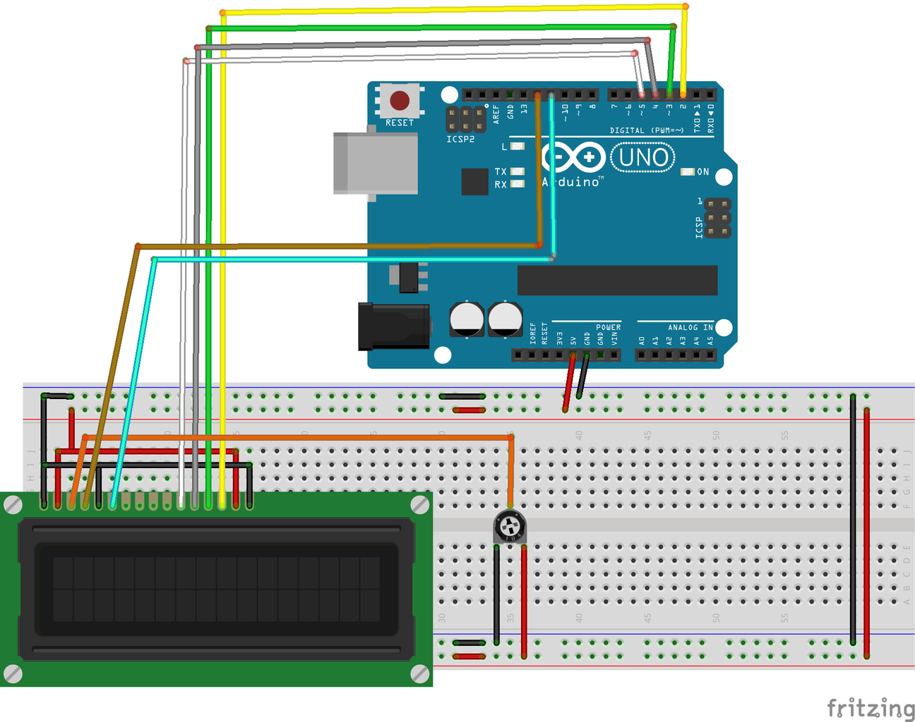
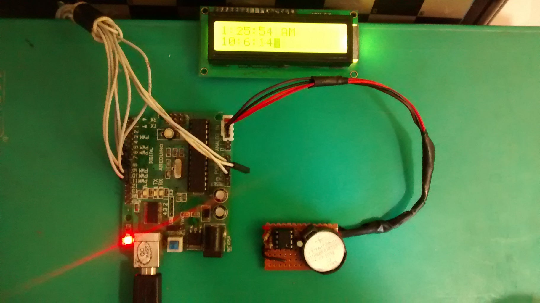
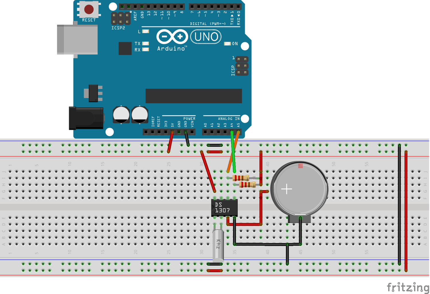
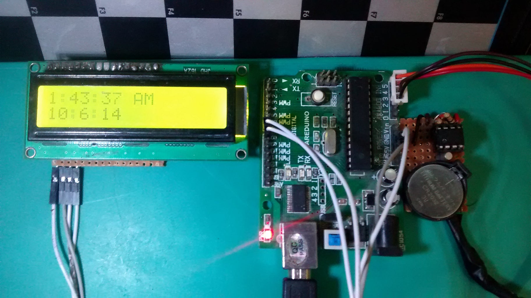
Now that the module is checked, now lets work on getting the time data to display on the LCD. The LCD module can be easily connected to the Arduino. The circuit diagram for connecting the LCD module is shown. The code for displaying the time is given below.
Before that I have made two versions of this code. One with the ordinary LCD connected to the Arduino. This is the simplest version but this will occupy most of the pins in the Arduino. So I came up with an alternative, using a Shift register to send data to the LCD module using only 2 pins. So you may choose whichever is more convenient for you.
Normal Version:
More pins but simpler!
So connect up the LCD as shown in the breadboard diagram. Then just upload the code into the Arduino and the date and time will be displayed in the LCD Display. So here's the code.
CODE:
#include <Wire.h>
#include <RealTimeClockDS1307.h>
#include <LiquidCrystal.h>
LiquidCrystal lcd(12, 11, 5, 4, 3, 2);
#define Display_Clock_Every_N_Seconds 10
#define Display_ShortHelp_Every_N_Seconds 60
String tz;
int hours = 0;
int minutes = 0;
int seconds = 0;
int dates = 0;
int months = 0;
int years = 0;
int ap = 0;
void setup() {
Serial.begin(9600);
lcd.begin(16,2);
pinMode(A3, OUTPUT);
digitalWrite(A3, HIGH);
pinMode(A2, OUTPUT);
digitalWrite(A2, LOW);
}
void loop() {
RTC.readClock();
if(ap == 1)
{
tz = "PM";
}
else
{
tz ="AM";
}
lcd.home();
hours = RTC.getHours();
minutes = RTC.getMinutes();
seconds = RTC.getSeconds();
ap = RTC.isPM();
dates = RTC.getDate();
months = RTC.getMonth();
years = RTC.getYear();
lcd.print(hours);
lcd.print(":");
lcd.print(minutes);
lcd.print(":");
lcd.print(seconds);
lcd.print(" ");
lcd.print(tz);
lcd.setCursor(0, 1);
lcd.print(dates);
lcd.print(":");
lcd.print(months);
lcd.print(":");
lcd.print(years);
delay(250);
lcd.clear();
lcd.home();
lcd.print(hours);
lcd.print(" ");
lcd.print(minutes);
lcd.print(" ");
lcd.print(seconds);
lcd.print(" ");
lcd.print(tz);
lcd.setCursor(0, 1);
lcd.print(dates);
lcd.print(" ");
lcd.print(months);
lcd.print(" ");
lcd.print(years);
delay(250);
lcd.clear();
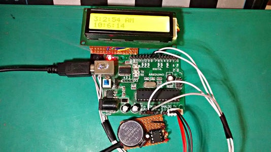
}After connecting the RTC module and uploading the code. The LCD will display the time in the top row and the date in the bottom row. This version is useful for learning the basic commands and let you to use these commands in your future projects.
Attachments
Step 7: Displaying the Time (Shift Register Version)

Shift Register LCD Version:
This version used The Shift Register module to send data to the LCD using only two pins instead of six pins. This module can be bought but I wanted to make it. The full instructions on making the module are given in this link COMING SOON!!!. So just connect the two pins of the Arduino to the module and upload the code given below and the same output will be observed like in the simple version.
CODE:
#include <Wire.h>
#include <RealTimeClockDS1307.h>
#include <LiquidCrystal_SR.h>

LiquidCrystal_SR lcd(8,7,TWO_WIRE);

#define Display_Clock_Every_N_Seconds 10
#define Display_ShortHelp_Every_N_Seconds 60
String tz;
int hours = 0;
int minutes = 0;
int seconds = 0;
int dates = 0;
int months = 0;
int years = 0;
int ap = 0;
void setup() {
//  Wire.begin();
  Serial.begin(9600);
  lcd.begin(16,2);

    pinMode(A3, OUTPUT);
  digitalWrite(A3, HIGH);
  pinMode(A2, OUTPUT);
  digitalWrite(A2, LOW);
}

void loop() {
  RTC.readClock();
    ap = RTC.isPM();
    if(ap == 1)
    {
    tz = "PM";
    }
    else
    {
    tz ="AM";
    }
    lcd.home();
    hours = RTC.getHours();
    minutes = RTC.getMinutes();
    seconds = RTC.getSeconds();
    dates = RTC.getDate();
    months = RTC.getMonth();
    years = RTC.getYear();
    lcd.print(hours);
    lcd.print(":");
    lcd.print(minutes);
    lcd.print(":");
    lcd.print(seconds);
    lcd.print(" ");
    lcd.print(tz);
    lcd.setCursor(0, 1);
    lcd.print(dates);
    lcd.print(":");
    lcd.print(months);
    lcd.print(":");
    lcd.print(years);
    delay(250);
    lcd.clear();
    lcd.home();
    lcd.print(hours);
    lcd.print(" ");
    lcd.print(minutes);
    lcd.print(" ");
    lcd.print(seconds);
    lcd.print(" ");
    lcd.print(tz);
    lcd.setCursor(0, 1);
    lcd.print(dates);
    lcd.print(" ");
    lcd.print(months);
    lcd.print(" ");
    lcd.print(years);
    delay(250);
    lcd.clear();
}
This second code uses a different library if you already have this module, please use this library for the above code to work.
We finally reached the end of this instructable. I hope that after reading this the viewer has obtained more than the basic knowledge of the DS1307 RTC Module. If you have any corrections or suggestions please comment below. Till next time bye.


