

Introduction: Arduino Uno DDS Audio Signal Generator


This is an update on my earlier Instructable: 10 Resistor Arduino Waveform Generator
https://www.instructables.com/id/10-Resister-Ardui...
It is motivated by comments from members AhmedS419 and BeenThereD where we discussed the possibility of creating a stand-alone mode without the need for commands from a USB connected PC and GUI.
In this Instructable I have modified the hardware and embedded software to provide both an independent stand-alone mode of operation, requiring only external power, and a PC connected GUI mode providing additional features. The project is now enclosed an a DIY Box.
Why DDS?
A basic Direct-Digital-Synthesis waveform generator outputs the amplitude corresponding to phase-values based on a phase_accumulator which is incremented by a phase_step at a frequency f_clock.
Compared to other Waveform Generators using the Arduino uno which directly output amplitude values based on a time-step using a timer interrupt at 100 kHz the current design permits a f_clock of ~400 kHz. Based on requiring at-least 8 sample points per waveform-cycle the effective usable output frequency would then be f_clock/8 or 50 kHz, compared to 100 kHz/8 or 12.5 kHz.
Additionally the DDS methodology provides a frequency-increment/setting-resolution for a 24 bit phase_accumulator of f_clock/2^24 or 0.024 Hz.
Specifications:
Stand-alone mode:
Frequency Setting: 1 Hz to 50 kHz in 1 Hz increments
Waveforms: Sin/Triangle and Square
Output: 0-5 V fixed
D/A converter: 6 Bit resolution
PC connected GUI mode
Frequency Setting: 0.05 Hz to 50 kHz in 0.05 Hz increments
Waveforms: Sin/Triangle/Ramp-up/Ramp-down/Arbitrary and Square
GUI: Windows VB.Net 2
Capabilities
The images provide a quick look at the waveform capabilities of this Signal Generator
Step 1: Arduino Pin Constraints and Connecting the Thumb-Wheel Switches

Pin Shortage
Implementing a 4 digit decimal setting for frequency using 4 Binary-Coded-Decimal (BCD) thumb-wheel switches, each requiring 4 pins and an additional common would require 17 I/O pins on the Arduino. Additionally, the 6-Bit DAC would require another 6 I/O pins. With some Arduino pins being allocated for supplies and ground, this number of I/O pins are not available.
It was necessary therefore to find a method of reducing the I/O pins required by the BCD thumb-wheel switches.
Workaround
I worked out a novel scheme based on using a simple capacitor-network circuit and software which needed only two I/O pins to read a hex-switch, leaving the remaining pins for other functions.
The detailed methodology was published as an 'Idea For Design' in the Electronic Design magazine:
http://www.electronicdesign.com/analog/hex-switch-...
We see here that only OCRA of the Arduino and one interrupt are used for decoding one BCD switch.
In this project I have extended this scheme using OCRA, four interrupts and common that is a total of only 6 I/O pins (compared to 17 ) to decode the 4 BCD switch values.
Please follow this Design Idea for a clear understanding of this scheme.
Attachments

Step 2: Circuit Schematics


The circuits can be divided int three groups:
- The BCD thumb-wheel switch decoding circuitry
- Switches required in the stand-alone mode
- And the Digital to Analog Converter
The first figure shows the basic switch block which is replicated four times in the second figure. The function of this portion of the circuit is as explained in the earlier step.
Three additional switches are used in the stand-alone mode:
A push-button switch connected to INT0 is used to update the frequency setting.
A SPST switch at Pin A0 sets the frequency multiplier X1 / X10
And a SPST switch at Pin A1 sets the waveform Sin/Triangle
The third figure is a simple 6-Bit 8:4:2:1 resistor based DAC which is connected to Port B of the Arduino.
Step 3: Circuit Wiring and Assembly


BCD Switch Components
For compactness the 8:4:2:1 weighted capacitor network for each BCD switch is directly wired at the switch terminals.
Four such switches are assembled together to set the 4 Digit Decimal frequency.
Circuitry
The rest of the circuitry is wired onto perforated-board as shown in the images.
Front Panel
The BCD switches, output terminals and other switches are assembled onto the front panel. These are connected to the perforated-board circuitry using mating connectors.
The details of the fabrication of the Box can be found at my Instructable:
Simple DIY Electronic Enclosure:
Step 4: Operational Modes

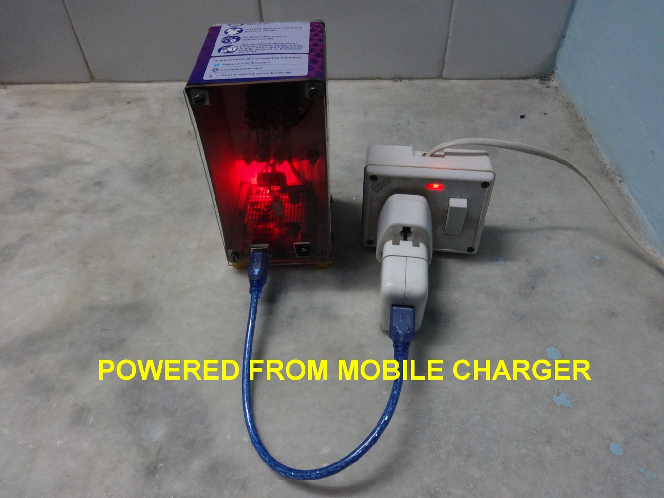


Stand-Alone Mode:
- The unit can be powered directly from a 5V USB mobile charger by connecting to the USB connector on the Arduino uno.
- Alternatively a mains operated DC supply of 6 V can be used to power the unit through the two-pin circular connector on the Arduino uno.
In these modes the frequency and waveforms are set by the front panel switches
PC Connected Mode:
The unit can be connected to a spare USB socket on a PC and powered and operated using the windows GUI.
Step 5: Software Windows & Linux


Arduino Code
The 010_BCD_SigGen.c code is implemented using Atmel Studio 6.0
The c-code implements a 24-Bit phase_accumulator of which the higher order 7-Bits are used as an address to a 128 step waveform table containing 6-Bit waveform data with values from 0x00 to 0x1F Hex.
Use the 010_BCD_SigGen.Hex to program the Arduino Uno using Avrdude.
GUI Software
Connect the Arduino uno to a PC USB port. Open up the Windows based GUI program attached.
The GUI program is easy to use:
It permits selection of the virtual com port (Try a second time if the port is not connected the first time)
Setting the output frequency
Selecting the waveform type
And running the program
In the special case of the DDS_Arb (0-50kHz) arbitrary waveform selection
The open file dialog looks for a .csv file which defines the arbitrary waveform
Once this is selected the waveform points are automatically uploaded
Run the arbitrary waveform at the frequency value selected.
Once loaded the waveform points remain in memory and if the same waveform need to be re-run we can cancel .csv selection.
Installation
To install the Windows GUI:
Extract the Windows GUI.rar to a suitable location on the PC to be used and Run the .exe file
That's it!The Windows GUI needs .Net 2.0 and has been tested on Win XP and Win 8.1
Arbitrary Waveforms
Arbitrary waveform data should be created as a .csv file containing one column of data with length 128. The data values should be in decimal whole numbers in the range 0 to 63. These values when loaded to the Arduino uno are converted to Hex values between 0x00 and 0x1F and output as arbitrary waveforms. Three typical waveforms with their corresponding .csv files are provided as examples.


