

Introduction: Arduino WiFi Set Clock With Analog Hands


I have built a number of clock circuits over the years. I recently modified a WiFi connected digital clock so that it would play Westminster chimes on the quarter hour, half hour and so on. This clock is described on my web page here:
http://www.trainelectronics.com/Arduino/LED_Matrix/Chimes/index.htm, on Instructables and on YouTube.
Step 1: Adding Hands

A digital clock with Westminster chimes is an interesting device but it really lacked one thing that you would expect to see on such a clock, HANDS! This realization brought me to the present clock implementation. I can't say that it was the most difficult project I have undertaken but it is surely one of the most time consuming (no pun intended). With most projects one can make a change to the software code and test it immediately. With this clock the best case was needing to wait for the minute hand to pass 12 (which took up to 59 minutes) or the worst case was waiting for a full day to pass before I could determine if the code change worked as expected.
Step 2: Enabaling Technologies
There were a number of things that enabled me to complete this clock project:
- The availability of inexpensive, geared stepper motors (I paid less than $15 for 5 of them, including the driver board, from Amazon)
- Access to a laser cutter that allowed me to design (in CorelDraw) the clock face, hands and the gears that connected the stepper motors and the hands.
- I also made some gears with my 3D printer. They worked well but took much, much longer to fabricate.
- A wonderful on-line program, http://geargenerator.com/ , that allowed me to design and download the gears that I needed
- The Wemos D1 WiFi development board that gets the current time from the Internet and sets the clock. It also plays the chimes.
- The DFPlayer MP3 player that provides the audio for the chimes
- Tiny rare earth magnets and small Hall Effect magnetic sensor devices that pinpoint the position of the hands on the clock face
Step 3: The Hands Mechanism

The two hands are animated with two small, geared stepper motors that I purchased from Amazon (see parts list). They come with driver boards that connect to four pins on the Arduino. I was able to use eight adjoining pins on the Arduino so connections are rather simple. In addition the driver boards need power. They are rated at 5 volts but I found that I could connect them to 7 volts to gain torque. If you are fortunate enough to build a low friction set of gears you can get away with 5 volts. 7 volts doesn't seem to do any harm as the motors are only powered on for a very short time every few seconds. The drive shaft of the stepper motor is flattened on two sides to facilitate attaching to a gear, see upper left inset.
Step 4:

In order to have two hands on the same central shaft I used two sections of brass tubing that fit one inside of the other. The outside diameters of the tubing are 1/8" and 3/32". In my first prototype these shafts were super glued to the center of two gears as shown here. The gears with the oval shaped cutout press onto the shaft on the stepper motor and the others are supported by the concentric brass shafts. I have made gears from plywood, upper left, clear acrylic, upper right, and Delrin, the black ones.
Step 5:
The gears that go from each stepper motor to the gears on the shafts are in a ratio of 1:1, which means for every step the stepper motor moves the gear and its associated shaft moves the same number of degrees.
Here lies the first major issue I ran into. The stepper motors are geared to improve torque and accuracy. The gear ratio in them determines the number of steps that must be completed to do one revolution. For these motors this turns out to be 512 steps per revolution. Why 512? If you deal with computers and programming you may have an idea as 512 is 2^9 (two to the 9th power), a nice "round" number to a computer. I had a devil of a time getting the clock to move its hands correctly because 512 does not divide by the number of minutes in an hour (60) or any of the numbers associated with time keeping. I did get the code to work but every hour I had to skip ahead a few ticks of the hands to keep proper time.
Since I had the ability to make gears of any size or tooth configuration it occurred to me that I could change the number of steps per revolution from 512 to something more "clock friendly" like 360. If I attached a 512 tooth gear to each stepper motor and a 360 tooth gear to each gear on the central shaft it would take six ticks of the stepper to move one minute with no more hourly adjustment issues! Problem solved & code simplified.
Step 6:

My current gear setup is shown here. You should be able to see that I didn't use a 512 and a 360 tooth gear, but a 64 tooth and a 45 tooth. A little math will tell you that the ratio is the same and the gears are stronger with larger teeth. (512 / 360 = 1.42222... and 64 / 45 = 1.42222...)
The white arrows point to the two small rare-earth magnets that allow the Arduino to know the position of the hands. More on that later.
Step 7:

The hands were also cut out with the laser cutter.
Step 8: Attaching the Hands

To attach the hands to the brass shafts, small collars with set screws were glued to each hand. These are called DUBRO collars. I used one with a 1/8" hole in the center and one with a 3/32" hole. The larger collar in the photo clearly shows the set screw and hex wrench that comes with the collars.
Step 9:

It is important that the collars be glued to the hands so that the shaft and hands are at 90 degrees to each other. Temporarily inserting a piece of tubing helps with this alignment. I used fast setting epoxy to glue the collars to the hands.
Step 10: Prototype

Here is one of the 4 prototypes I built. The clock face was also done on the laser cutter. The large gear at the top was made of acrylic so that the number "12" would not be obscured
Step 11:


My latest clock face was made by having the laser cutter cut out each numeral so that I could paint them red then reinsert them in the face.
I saved the holes and glued them in after painting.
Once the paint was dry the numerals were reinserted and glued from the back.
Step 12: Mounting the Stepper Motors

The stepper motors are attached to the clock face with four 2-56 x 1/2" flat head machine screws & nuts. Note the shape of the shafts on the stepper motors. They allow for a good force-fit of the gears.
Step 13:

The stepper motors extend from the back of the clock face. Note the large hole in the area between the two motors. That allows us to adjust the placement of the central gear shaft so that the gears mesh smoothly.
Step 14: Mounting Gears & Hands

The 64 tooth gears go onto the shafts of the stepper motors. The larger one at the top (so that it partially covers "12") and the smaller to the left.The smaller 64 tooth gear meshes with the upper gear on the central shaft so I used a small wood spacer to raise it a bit. (the spacer is circled in red)
Step 15:

Note that the gear on the left is flush with the top of the stepper motor shaft and the one on the right is down about 1/8".
Step 16:

In order to get a tight fit when inserting the brass shafts I cut the holes in the gears a bit undersized and reamed them out by hand with a 1/8" bit (smaller gear) and a 3/32" bit (larger gear).
Step 17:

The center brass shaft will go into the small piece of brass shown here & marked with a red arrow.
Step 18:

This piece of brass is attached to a long, rectangular piece of plywood on the back of the clock. The oval cutouts are there to allow clearance of the stepper mounting screws. This piece of wood can be moved about until the two sets of gears mesh with little friction. Once the right placement is found permanently attach this to the back of the clock with small wood screws. Be careful that they don't pierce the front of the clock.
Step 19:

The larger central gear has the 3/32" shaft going through it. The small washer separates the two gears reducing rubbing and excessive friction.
Step 20:

Here the smaller gear, with the 1/8" shaft, is placed over the smaller shaft. Make sure there is minimal rubbing - the two pieces of brass should rotate smoothly. My larger brass shaft is 3/4" long. The smaller shaft is about 1.5" long as it must protrude out of the larger shaft at the top and it must go into the support shaft at the bottom.
Step 21:

The smaller tube can be seen more clearly here along with the way it extends out of the top and bottom of the larger shaft.
Step 22: Magnets & Hall Effect Sensors

One of the down sides of using stepper motors for any project is the fact that the controller doesn't know exactly where the motor is on its journey. All you can do is send step commands but if you don't know where the motor started you can't tell where it is at any given time.To overcome that shortcoming a pair of magnets are inserted in small holes in the smaller gears on the central shaft. They are used to stimulate a pair of Hall Effect sensors that can detect a near-by magnetic field.
The magnets that I used are 1/8" in diameter and 1/8" thick. Other sizes are sure to work. The important thing is to place them on the gears so that the south pole points up.
Step 23:
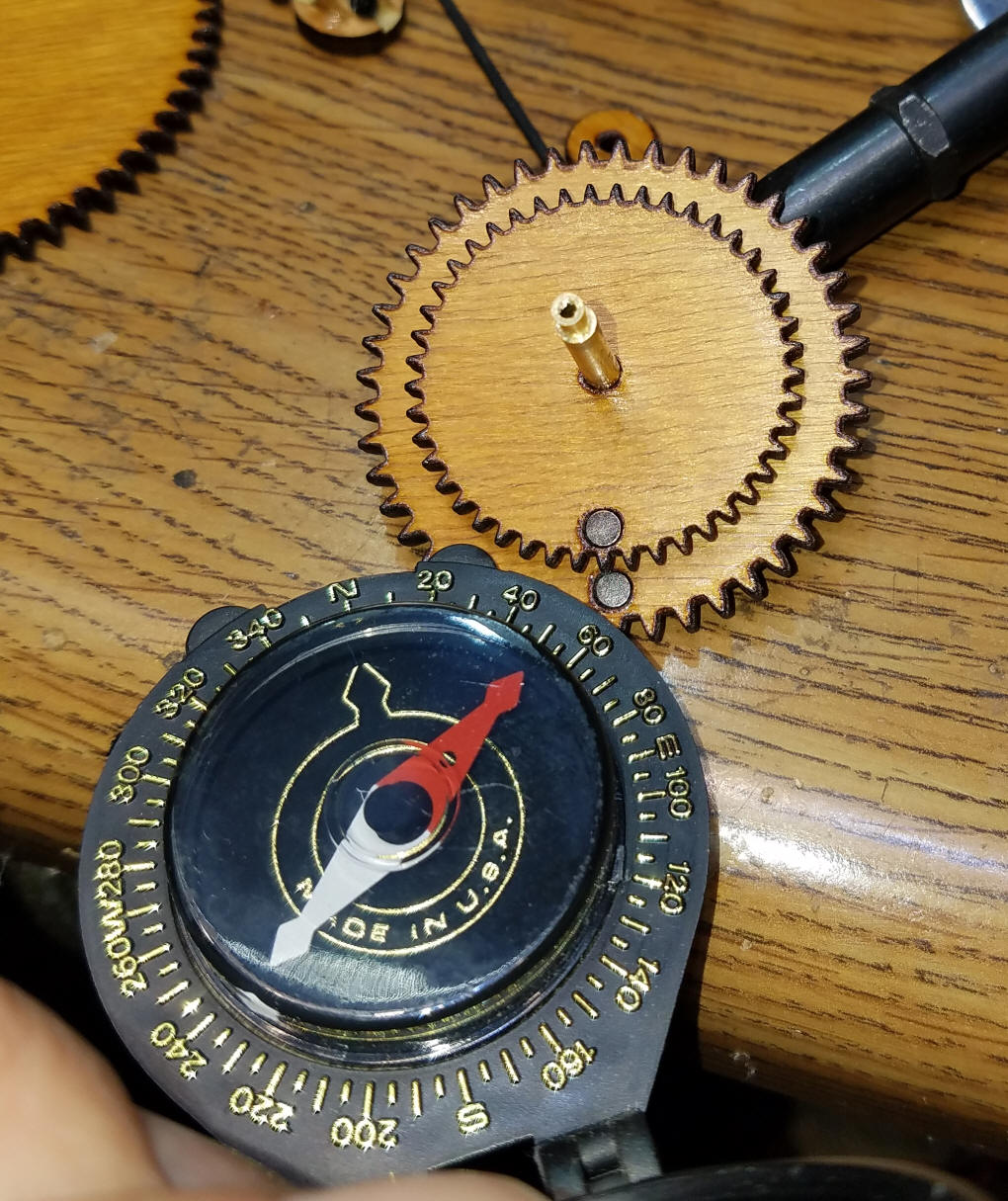
You can use a magnetic compass to determine north and south poles. In this photo the arrow points to the south pole.
Step 24: Hall Sensors

The magnetic sensor, called a Hall Effect Sensor, is shown here. It has three leads, one for +5 volts, one for ground and one that is the output of the sensor. That lead needs to be pulled high with a 10 K resistor. Rather than putting that resistor on the circuit board I generally solder them at the sensor as shown here. The resistor goes between the two outside terminals.
The side of the sensor that has a label on it goes towards the magnet with its south pole up. This can also be seen by the shape of the sensor which is tapered on the side with the label.
Step 25:

If you prefer you can use a 10K surface mount resistor as shown in this photo. The connections are still to the outer two leads as the center lead touches the insulated part of the resistor.
Step 26:

The Hall sensors are placed so that one sits just above where the upper magnet will pass and the other sits just above where the lower magnet will pass. In each case the tapered, label side is facing down towards the magnets. Once I got them in place they were glued to the clock face.
Step 27:
That completes the clock face. There will be a number of wires on the back of the clock. Two pairs of 3 wires from the Hall sensors and two pairs of 5 wires coming from the stepper motors.
Step 28: Parts
- 2 @ Stepper Motors with controller- Amazon (5 for about $15) or eBay
- 2 @ hall sensors - Amazon or eBay
- 2 @ small magnets - junk box or http://www.kjmagnetics.com/proddetail.asp?prod=D2...
- 64 tooth gear - large - junk box, 3D printer, laser cutter
- 45 tooth gear - large -junk box, 3D printer, laser cutter
- 64 tooth gear - smaller -junk box, 3D printer, laser cutter
- 45 tooth gear - smaller -junk box, 3D printer, laser cutter
- clock face - 3D printer, laser cutter
- Brass tubing - 1/8" diameter - 1 piece about 3/4" long - Amazon or eBay or hardware store
- Brass tubing - 3/32" diameter - 1 piece about 1.5" long and 1 piece about 5/8" long - Amazon or eBay or hardware store
- DUBRO collar - 1/8" - Amazon or eBay
- DUBRO collar - 3/32" or 1/16", drilled out to 3/32" - Amazon or eBay
- minute hand - 3D printer, laser cutter or hand cut
- hour hand - 3D printer, laser cutter or hand cut
- Wemos D1 - Amazon or eBay
- Arduino Pro Mini - Amazon or eBay
- DFPlayer - Amazon and BangGood
- Micro SD Card - 1 or 2 gig (for DFPlayer) - junk box, Amazon or eBay
Step 29: The Arduino Hardware
While it might be possible to get this clock working with just an ESP8266, the board that connects to WiFi to set the clock's time, I found that using both an Arduino Pro Mini and a Wemos D1 gave me more flexibility and more pins to connect to the clock mechanism. The prototype clock circuits were build on circuit board that I designed for another purpose. It did have accommodations for both the Pro Mini and the DFPlayer so very few modifications were needed to adapt it to the clock.
Step 30:
Detailed information on the DFPlayer and the MP3 files that are used for the Westminster Chimes is on my web page here: http://www.trainelectronics.com/Arduino/LED_Matrix/Chimes/index.htm
This page includes a link to download the MP3 files that I used.
Step 31: Components


The main components that are used are shown in the next two photos. The circuit board needs minor modifications to work with the clock. Clockwise from the upper left: Arduino Pro Mini, DFPlayer, 1 GB micro SD card, Wemos D1, circuit board, 10uf tantalum cap, and a 7805 voltage regulator.
Step 32: Combine Boards

To simplify wiring and make a more secure circuit I opted to attach all four boards together with hot glue and wooden rods.
Step 33: Schematic

The wiring diagram shows the two stepper motors, the Pro Mini, the DFPlayer, the Wemos D1 and the two Hall Effect sensors and how they are all wired together. Note that the stepper motors work from the same 5 volt power supply that operates the rest of the circuit.
This makes things much simpler! If you opt to use 6 or 7 volts for the steppers just be sure to have a common ground to the rest of the circuit.
Step 34: The Electronics

I built the main board, that houses the power supply, Pro Mini and DFPlayer using a circuit board that I designed for another project. My notes on using that board are shown here. You could also use a prototyping board and solder wires to connect the various pins on the circuit.The three traces that need to be cut on the top of the board are shown here...
Step 35:

... and the five on the back are here.
Step 36:

The wiring on the back is shown here. The resistor between the TX on the Wemos D1 and the RX on the DFPlayer is in a piece of clear tubing to insulate it. The larger sized red & black wires connect +5 and ground from board-to-board. The thin blue wires go to the Hall sensor pins and the small white wires go to the DFPlayer and Wemos D1.
Step 37:

Here is the back of the clock showing the two stepper motors. The diagonal strip of wood is the one that supports the central shaft. The two small black screws secure it to the clock face.
Step 38: Initial Setup
When you first run the program the hands will rotate until each magnet is detected. At this point the hands should both be straight up pointing to 12. If they are not, disconnect the power, loosen the set screws and align them properly. Make sure that you have inserted your WiFi SSID and password into the Wemos program. Once the hands are aligned and the network is identified the clock should set the hands based on the current time.
There are a number of Serial print statements in the code that can be used to debug any issues you might have. Just use the IDE's serial monitor to view them - the baud rate needs to be set to 9600
Step 39: Accuracy
The clock is quite accurate due to its getting the time from an Internet time server. The hands do have some backlash, play or "slop" in their movements due to imperfections in the inexpensive stepper motors. You can easily move the hands a minute or two either way.
Step 40: Improvements
- reset at midnight (or some other hour)
- restrict chimes to waking hours
- larger clock face
Step 41: Clock & Gear Files
The laser cut parts of the clock were designed in CorelDraw and cut with a generic eBay laser cutter. This laser cutter interfaces directly with CorelDraw. The file I made is here:
StepperMotor-9-ratio-change-ALL-V4.cdr You can print to most laser cutters from a PDF file, too - a PDF version of the file is here:
Arduino/Clock_stepper_hands/images/StepperMotor-9-ratio-change-ALL-V4-PDF.pdf
The gears and hands could also be printed on a 3D printer. The PDF file should help with this.
There are two Arduino files. The first one is for the Wemos D1. You can download it here:
http://www.trainelectronics.com/Arduino/Clock_stepper_hands/Wemos-from-chimes-sendEpoch-v2-0-esp.zip
The file for the Pro Mini is here:
Both of these files are stored on my web page (TrainElectronics.com) and will be updated as the software is updated.
Step 42: Conclusion
I think you will find the end result of this project to be an interesting & pleasing clock. I hope gives you as much satisfaction as it has given me.
If you build one please send me a photo and your impressions of the unit. While the code provided here does work well I am also sure that it can be improved.
If you make any changes to the code that you would like to share please let me know.
Enjoy!
