

Introduction: Arduino Wireless Control Robot Car
In this post you are going to learn about how to build an Arduino wireless control robot car. We will build both the transmitter and receiver sides.
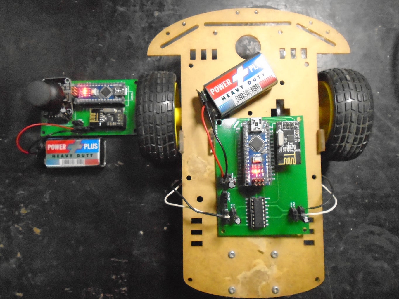
The transmitter side will include an Arduino nano, joystick module and NRF24L01 to send the data wirelessly. The receiver side will include Arduino nano, NRF24L01 to receive the data and L293D motor driver IC to control the motors. Both the transmitter and receiver circuits will be powered by 9V batteries.
Components Required
The components you are going to require for this project are as follows
Transmitter side
- Arduino Nano
- Joystick Module
- NRF24L01
- 100uf capacitor
- 3 pin Slide Switch
- 2 pin terminal block
- 9V battery
Receiver side
- Arduino Nano
- NRF24L01
- 100uf capacitor
- 0.1uf Capacitor
- 10uf capacitor
- 3 pin Slide Switch
- 2 pin terminal blocks (3 pieces)
- L293D Motor Driver IC
- 9V battery
Step 1: Circuit Diagram

The main part of both transmitter and receiver circuits is Arduino nano which is powered by the 9V battery. Then we have got NRF24L01 module on both sides to communicate wirelessly.
Joystick module on the transmitter side will be used to get the x and y values that will be sent to the receiver side and will be used to control the motors. L293D motor driver IC on the receiver side will also get power from 9v power supply and will control the motors.
Using the above circuit diagram, you can make the circuit on breadboard to make sure everything works as you want it to.
Step 2: PCB Design


After making sure everything works fine on the breadboard, I have designed the PCB on EasyEDA. EasyEDA is an open-source online PCB Design Tool.
Here’s a link to the PCB design of this project. After designing the PCB’s, I generated the Gerber files needed for manufacturing of PCB’s.
You can download the Gerber files through following links
Step 3: Ordering the PCBs

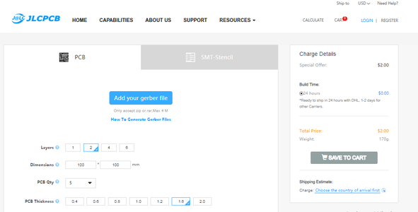


Now we have got the PCB design and it’s time to order the PCB’s. For that, you just have to go to JLCPCB.com, and click on “QUOTE NOW” button.
JLCPCB are also sponsor of this project. JLCPCB (Shenzhen JLC Electronics Co., Ltd.), is the largest PCB prototype enterprise in China and a high-tech manufacturer specializing in quick PCB prototype and small-batch PCB production. You can order a minimum of 5 PCBs for just $2.
To get the PCB manufactured, upload the gerber file you downloaded in the last step. Upload the .zip file or you can also drag and drop the gerber files.
After uploading the zip file, you’ll see a success message at the bottom if the file is successfully uploaded. You can review the PCB in the Gerber viewer to make sure everything is good.
You can view both top and bottom of the PCB.
After making sure our PCB looks good, we can now place the order at a reasonable price. You can order 5 PCBs for just $2 but if it’s your first order then you can get 10 PCBs for $2.
To place the order, click on “SAVE TO CART” button.
My PCBs took 2 days to get manufactured and arrived within a week using DHL delivery option. PCBs were well packed and the quality was really good.
After assembling everything and connecting the motors, it looks as shown in last image on this step.
Step 4: Code
Transmitter Code
First, we need to include the SPI and RF24 library for wireless communication. Then we need to define the digital pins for NRF24L01 module and analog pins for joystick module. After that we need to define radio object, communication address for it and an array to store joystick module values in it.
In the setup function, we need to initialize the serial and radio communication.
In the loop function, we first read the values from the joystick module and stored them in the array. After that, using the radio.write() function we will send that message to the receiver. The first argument in this function is the message and the second argument is the number of bytes present in that message.
The radio.write() function returns a bool and it is true then it means that the data reached the receiver and if it returns false, data has been lost.
Receiver Code
On the receiver side, we also need to include the SPI and RF24 libraries for wireless communication. Then we need to define the digital pins for NRF24L01 module and l293d motor driver IC and some variables. After that we need to define radio object, communication address for it and an array to store incoming values in it.
In the setup function, we need to initialize the serial and radio communication. Then we need to define some pins of L293D as output pins.
In the loop function, we first check if some information is available or not. If it will be there then we will store it in variables. After that we will control motors according to these values.
You can also get the codes at https://electronicshobbyists.com/arduino-wireless-control-robot-car/


![Tim's Mechanical Spider Leg [LU9685-20CU]](https://content.instructables.com/FFB/5R4I/LVKZ6G6R/FFB5R4ILVKZ6G6R.png?auto=webp&crop=1.2%3A1&frame=1&width=306)


