

Introduction: Bicycle - Powered Arduino Water Purification System (using UVC Light)


This instructable demonstrates how to power a UV-C water purification system with a bicycle and arduino control. A dynamo in the rear of the bicycle charges a battery (which we have initially charged already for this project) that runs the arduino and the light.
Most of the steps are inspired from other instructables and projects which are recommended to review in addition to what is written here. The steps here will not go in depth as to how to setup arduino or the different associated projects you can find elsewhere.
An additional optional step demonstrates how you would add a pump and filter to the system through a second bottle.
This is not a guaranteed way to purify your water but is meant as a demonstration as a prototype to inspire further efforts in bicycle-powered and portable water purification.
Helpful related instructables:
https://www.instructables.com/id/WATER-LEVEL-INDICA...
https://www.instructables.com/id/Controlling-AC-lig...
https://www.instructables.com/id/Arduino-Battery-Vo...
Also I would like to thank my father and collaborator on this project for assisting remotely (and following alongside with a parallel project implementing the pump system) from across the ocean: https://www.instructables.com/member/KlausM5
and Cykelköket Solna for their assistance in letting me use their workspace to build up a discarded blue bike frame I found on the road in Skanstull
Step 1: Materials


There are several larger things you need for this project and quite a few small things.
Arduino Starter Kit (with LCD display, jumper cables. potentiometer, etc)
bridge rectifier
Universal AC/DC adjustable Power Module/ Regulator (step up) Booster LM2577 (you can also replace the rectifier with this if you choose to place the booster there)LML
25-50V capacitor, 1000uF (minimum)(not necessary if above Power module is used)
6V bicycle dynamo (12V works also, but regulator is recommended then)
alligator clips (for prototype testing, replace with wires of appropriate gauge for final wiring)
UV-C lamp, 5-7 watts, with ballast (important!) you can get one for an aquarium that comes in a tube and you can unscrew
Car power inverter with cigarette lighter plug input, converts 12V DC to 120V or 220V AC (depending on your light/what country you are in or buying the light from) from eBay or auto supply store
Cigarette lighter adapter socket with pig tail wires, from eBay or auto supply store
Relay (2, 4 or 8 channel) for Arduino (eBay or other sources)
2x 2.1 x 5.5mm DC Power Male Connector Plug with screw terminals (one to interface with the Arduino, one is optional) http://www.amazon.com/2-1mm-5-5mm-Male-Power-Adapter/dp/B002QWNZHU/ref=sr_1_2?s=electronics&ie=UTF8&qid=1463706955&sr=1-2&keywords=2.1+x+5.5mm+DC+Power+Male+Connector+Plug
CD4049 hex inverter http://www.digikey.com/product-detail/en/texas-instruments/CD4049UBE/296-2055-5-ND/67301
buck /boost regulator circuit (possibly)
3x 10kΩ 1% resistors or 5%, selected for close match in resistance and accuracy
1x 1MΩ resistor 5% or 10% (add more for additional water level sensors, up to 6 total)
2 mini breadboards
bicycle with 2 baskets (and rear cargo rack)
1 bottle with a lid you can drill through (used a 1L Nalgene here and a spare lid)
additional 24 gauge (0.51mm dia.) cable, same thickness as Arduino cable
20 gauge (0.81mm dia.) cables for battery power connection to buck/boost regulator
zip ties
cardboard, thick
a dark cover, aluminum lined is fine, to put over the light and 1L bottle
optional for pump setup:
Water pump (car windshield washer pump with 1/4" or 6 mm dia. inlets/outlets)
1/4" or 6 mm I.D. PVC tubing (or other that fits the pump)
6mm O.D. hose connectors, straight, angle, T and Y (type and number depending on flexibility needed for routing of tubing. see image for example)
a jug that you can cut and drill hole near bottom (i.e. 1 gal. milk jug)
Filter. We used an Aquamira filter Frontier Green Line filter (see image)
F2-type connectors to fit the pump for cables if it doesn't already come with those
Step 2: Battery Charging: Rectifier Circuit to a Dynamo


This circuit is simply a bridge rectifier and a capacitor.
the ~ ends of the rectifier go to the dynamo, it doesn't matter which goes to which terminal.
the plus side of the rectifier should connect to the plus of the capacitor, the minus of the rectifier to the minus of the capacitor. from there there should be + and - outputs that will go to the battery.
With a breadboard remember to place connections in the same row. so each pin of the rectifier should be in a different row, but initially you won't have to solder while you are testing this.
Step 3: Arduino: Powering the Arduino

In order to power the arduino from a 12V source, we used a female 12V DC socket with terminals for wires (pictured) to connect to the arduino's 12V input. The arduino can take up to 12V. If you are concerned that the battery may produce too much voltage (14V, etc) use a buck booster circuit in parallel (pictured connected, that's the blue board) to keep the voltage at 12V. You turn the potentiometer on the booster with a screwdriver until it is at 12V. With our's this was at its limit, when it clicked.
The code used for a demo of this project is attached above. You can further modify it to use the pump (if you have any difficulty doing this please contact me or my collaborator!)
Attachments

Step 4: Arduino: LCD Display

There are tutorials online for hooking up the LCD display to the arduino, and sample exercises in the book that comes with the kit involving this. One thing to be wary of is that you will need the space for other components on the board such as the hex inverter, so try to consolidate the LCD components to a small section of the board instead of the middle as is depicted in these tutorials. We will not provide an overview as to how to do this here!
Here is a basic LCD tutorial from Arduino: https://www.arduino.cc/en/Tutorial/HelloWorld
Step 5: Arduino: Water Level Sensing

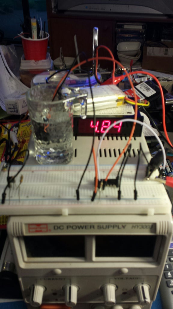


To sense the water level you will need 2 wires and a hex inverter. Since you already have an LCD display on your breadboard, placing the hex inverter so it doesn't interfere with the LCD is the most difficult aspect of this. You can see a diagram of how to hook up the hex inverter above.
One of the two water level wires is ground and goes to the bottom of the plastic bottle, touching the bottle. The other wire is your input that goes on the other side of the hex inverter (close to the hex) of the 1MΩ resistor. Your second pin should go to whichever arduino digital data input you selectd (here we chose "7"). The first pin goes to plus on the arduino. The last pin goes to minus. If you want to sense more water levels, you can use additional pins. We only wanted to sense when the water was almost empty for the possibility of stopping and starting the pump.
The picture depicts a test with a small glass of water (and a separate circuit than the original one to the left).
In this case 5V or high indicates contact with water. Low indicates no water. The sensor is sensitive enough to detect skin moisture as "high".
Ideally, the water level sensing will work with the pump setup in the first bottle, not with the light in the second bottle. We found that when the wires are in the bottle with the UV light that there was significant interference to the arduino while the light was on. If you don't plan on implementing the pump and first bottle, omit this, unless you want to find a way around the interference (everything will work except the arduino LCD display when the interference occurs).
The way we envisioned this originally was that the arduino would sense when there was no water left in the first bottle, shut off the pump, and then after a small delay turn on the light in the second bottle for some time. If you are just planning on using the light and one bottle the water level sensor is thus not necessary.
Step 6: Arduino: Relays


In order to hook up the relay, you need to know the pin out of your relay module. The one here has different inputs (in1, in2, in3, in4). The one corresponding to your device should connect to the data pin you desire on the arduino. Ground connects to arduino ground. VCC connects to 5V or the arduino +. It doesn't provide power to the relay.
Then, on the other side of the blue blocks are screw terminals. One is NC, one is NO (never closed and never open) and another is your power output to the device. Here, the NC is in the middle, and it connects to the same booster board that the system uses, on the plus side. The output to the device (the power inverter for the light) is on the left side of it and connects to the plus side of the power inverter (we used a cigarette lighter adapter that comes with two wires on it for wiring in car systems). The minus of the power inverter connects to ground.
See image from johnny-five.io of how to connect the relay and our hand drawn version as well. Different relays will have different diagrams on how to connect them, this may not be applicable to your's.
Step 7: Battery Voltage Checking


For the voltage checking you need 3 resistors of equal resistance in series, with an output from the end row of the second resistor to an analog pin of the arduino. Plus goes on one side, minus on the other of the circuit (make sure these are in the same rows as the resistor legs, and that the end leg of one resistor is in the same row as the start leg of the next resistor). Plus should go to the battery plus, before the booster. Minus can connect to ground on the arduino breadboard.
Check the resistor readings with an ohm meter to find 3 with the closest possible reading. We used 3x 10 kΩ
Step 8: Bicycle: Attaching Baskets and Routing Cables


We used a large basket in the back for the battery and rectifier circuit and a smaller one in the front for the water bottle with UVC light, plus cardboard zip tied to the handlebars to hold the arduino. Long plus and minus cables were routed along the bike frame with zip ties from the battery to the arduino, which we simply placed on a piece of cardboard zip-tied to the handlebars. A more long-term and weather proof solution could be developed than this!
No picture is provided of the battery hooked up itself, the plus and minus are considered evident there, which you attach the output of the rectifier & capacitor circuit to, as well as the cables that are routed to the front of the bike along the frame. Alligator clips were used to make the connections to the circuit and to the extended cables.
Step 9: Water System: Cut Holes in Lids


Two lids were cut for the project, including one for the optional pump system. The first lid was sized to firmly hold the UVC light with a second hole for future tubing from the pump. The second was cut with 2 holes to hold tubing, as depicted. A drill was used for the holes.
Step 10: Water System: Add the Light


Plug the UVC light to the power inverter that you have hooked up to the arduino (with the arduino and system off). The bulb should fit in the lid hole you have made tightly enough to not move. Make sure only the bulb is in contact with the water, nothing else, the rest of the ballast should be out of the water.
We shielded the light ballast that was out of the water with cardboard and electrical tape. But, the bottle itself needed shielding as well. The bag pictured was not sufficient for the light, just the bottle, as some of the UV-C light escaped the top of the bottle. Thus, you need a thick material that covers all possible areas sufficiently. This is IMPORTANT as UV-C can be very damaging to the eyes! Make sure to cover the bottle all the way up, including the lid, sufficiently.
Step 11: Optional: Pump Setup (and Make a Container)


In order to attach the pump you want to make sure that the container you use will be sealed with grommets at the holes to plug them.
A gallon jug was used here for the container and appropriate sized holes cut for the pump.
Connectors for the power can be placed in the pump as depicted (we used connectors from an F2 connector set) but make sure they don't touch in the pump!
Step 12: Optional: Add Tubing


As part of the pump system, you will need to add tubing. Cut an appropriate length for both the inlet and the outlet of the pump. The outlet should go to your second bottle, through the hole you cut in the lid to fit the tubing. You will place the filter in line after the pump. Use small pieces of tubing here. Any bends should be replaced with the housing connectors previously mentioned
Step 13: Testing and Setup


To test you can place the bike on a bike trainer (but disengage the rear rolling wheel if so - see image prior to project of bike setup on trainer).
Test the setup without the light connected first. Make sure the relay turns on and off. Test the light separately to make sure it has no flaws and to be aware of how bright it is - make sure you do not look at it, cover the light completely, and have precautions taken for this.
Ensure that you will not be touching the electrical components or near the light during the first trials to make sure it is running smoothly.
Step 14: Complete!


Enjoy your prototype mini water purification system as you ride around your town. And it you get time, modify this and post what you did in the comments!
www.vijverinsite.nl and healthyhomefilterco.wordpress.com are the sources of the images of the UV lamp - we didn't want to take a picture since it is bad for the eyes
