

Introduction: Breadboard and LED


Setting up the LED and Breadboard is easy. This is all from Kit 1: Introduction to Electronic Circuits of Real Circuits LLC.
Step 1: How the Breadboard Works

The bus terminals are the long strips on the side and the terminal strips are the short strips in the middle where you will be building your circuit.
Step 2: Connecting the Bus Strips Together

The Bus strips are separated at the 30th row in this breadboard. Some breadboard are connected all the way down the side. You also must connect each of the bus terminal on either side to one another if you want to be able to plug in to the power and ground anywhere on the breadboard.
Step 3: How NOT to Power Breadboard

Creating a short circuit means that the power or current is flowing from the battery pack uncontrollable. The battery pack will possibly melt or the batteries could pop. Just make sure not to connect the wires from the battery pack to the same terminal or make sure the the current can not flow unless it first goes through a resistor or Integrated ciruit first.
Step 4: Powering Breadboard Safely
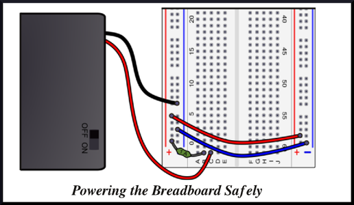
I like to use a little 1 Amp fuse. This will protect the battery pack and circuit. If you do not a fuse, its okay just be sure to connect the black wire to the blue bus terminal or ground and the red wire to the red bus terminal.
Step 5: Reading Resistors

To power the LED, you need to select an LED from 220 Ohms to 10,000 Ohms. The lower the resistance the brighter the LED will be.
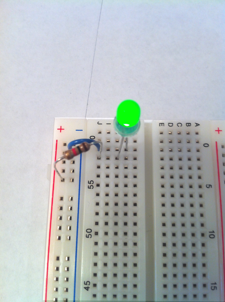
Step 6: LED Circuit

The long wire lead of the LED is the red lead in the picture above, and the short wire lead is the blue lead in the picture above. It will not light up if it is oriented incorrectly.
Step 7: LED ON
If everything is hooked up right and the power is on then the LED should light up. If you would like to learn more visit RealCircuits.com.


