

Introduction: Build a Multi-Voltage Portable Power Supply You Can Take Anywhere


In this tutroial I'll show you how to build - an ultra-convenient, portable bench-top power supply you can take anywhere. It's powered by 8 AA batteries so you never need to worry about travel adapters and it's ultra-light for flying!
The shopping list
This is a long list, but the components themselves are wonderfully cheap, especially if you can buy from a hardware or electrical supplies shop. Put together, it'll cost about £20 in total.
- You will need:
- 3-way switch (x1)
- Resistors
- 220Ω (x1)
- LED (x1)
- Capacitors
- 10µF electrolytic (x5)
- 0.1µF ceramic (x3)
- Voltage regulators
- LM7809, 9V (x2)
- LM7805, 5V (x1)
- LD1117-3.3, 3.3V (x1)
- Perf board / PCB (preferably tracked, approximately 70x45mm) (x1)
- Wires (x1 pack)Heat shrink tubing (optional but recommended) (x1)
- Battery compartment (8xAA, preferably with 9V connector) (x1)
- 9V connector lead (if you have the above battery compartment) (x1)
- Shotkey diode (x3)
- Project box (buy this last after you have your finished board, battery compartment ) (x1)
- You'll also need connectors to get the power out to your project.
Usage notes (for Arduino):
Please note that the +5V supply should not be connected to an Arduino's 5V Vcc simultaneously with any other power source. This includes power from USB. Therefore, please use the 9V rail through Vin or the DC connector, or disconnect the supply before connecting to USB.
Step 1: Understanding the Circuitry


My implementation is a composite of three linear regulator circuits, giving three readily available voltages. The basic (one voltage) circuit shown below, is the standard circuit used everywhere. Here is a really good video explanation of the basic circuit and the theory behind it, produced by Afrotechmods.
The supply subsystem picture above shows you the basic linear regulator circuit. The circuit gives you a nice even voltage that is great for low-load applications, such as your Arduino projects. Linear regulators are commonly rated up to 1A.
This build is made up of four subsystems. The first is the DC power supply from the battery pack, with the first filtering capacitor (leftmost C1 in the basic circuit) and a power switch (power subsystem diagram). The filtering capacitor does the job for all the regulator subsystems, so we only need it once.
Next is our 9V regulator circuit (9V subsystem diagram). This produces our 9V output rail, which the 9V connectors or leads will connect to.
The 5V subsystem input connects to the same place as that of the 9V subsystem (5V subsystem diagram). These operate in parallel so that load on the 9V rail cannot compromise the 5V supply. The output is a good place to put your power LED. You can see the 5V regulator is preceded by a 9V regulator. The greater the voltage drop, the greater the heat output from the regulators. As such, going from 12V to 5V will cause some heat buildup. We can share the load and thus heat output by using an intermediary voltage step with the 9V regulator, only loaded by the 5V regulator. The capacitor between them helps to prevent any ripple superposition between the two regulators (just for good measure). The 5V and 3.3V rails should only really be supplying light-current circuits; nothing too strenuous. So finally, the 3.3V supply can be stepped off the 5V rail, giving us the fourth subsystem (3V3 subsystem diagram).
Each output rail has two capacitors to filter high and low frequency noise (ripples) from their respective regulators. A shotkey diode can also be put in reverse, parallel with the output capacitors on each rail. This ensures circuits producing back-building voltages don't blow anything up. Put it all together and you end up with the total schematic shown above.
Step 2: Soldering

When you do your soldering, space the individual regulators apart to aid heat dissipation. A few centimeters is fine. You'll want to keep your filtering capacitors as close to their regulators as possible, preferably in front if you want to attach a heat-sink to the back (flat) side. Your regulator's 'GND' pin should be in the middle, so also ensure the negative (striped) pin on the 10µF capacitors orients to the middle of the regulator. If you have side-by-side tracks on your perf board, you can place the 'GND' and 'OUTPUT' pins on the tracks. All this can be seen above.
When soldering the battery compartment, I recommend a way of making it detachable from your main board. If you have the 9V connector on the battery holder and the connector that is fine. If not, I recommend putting connectors between the battery box and the board. That way, you can detach the whole battery holder without desoldering it. If you decide to use PCB headers to output your voltage rails, solder them onto a separate board so that you can mount them flat to the inside of your project box. Now you know how much room you need for your board, heat-sinks and batteries, it's a good time to get your project box. Don't forget you need room to mount your switch, LED and ports, as well as allow heat buildup, so ensure you have some excess room.
Step 3: Mounting the Components


I'll leave the external layout and aesthetics to you. Just remember to use heat-shrink tubing whenever you solder cables to terminals (like on the power switch) to avoid shorts. It's also a good idea to allow your PCB to be removable. Sticky cable clips can be used to make a slot for my board to sit into.
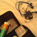
You can also see that the board acts as a divider. That way, if the batteries move they don't damage the upright components. If your layout matches the one above, add a block of sponge to the battery section for cushioning. That way the batteries are elevated above the external cables' ports and pressed to the lid, securing them once closed. Remember, the batteries together are heavy so need to be secure. My final product (above) had 9V and 5V outputs, with space to add the 3.3V regulator and cables later if I decide to.
So, there you have it. A 9V, 5V and 3.3V stable supply that you can take anywhere with no country adapters or spare cables. If you're flying and weight is an issue, you can always pop the batteries out making it super light.
Acknowledgements
- Lots of thanks to Afrotechmods for really great videos explaining voltage regulator circuits. I really recommend these.
- Thanks also to this Altoids Tin build for your inspiring design.


