

Introduction: CBDBv2 Evolution - ESP8266 Development Board Meets ARDUINO IDE!


The Internet of Things revolution is here!
IOT describes a world in which everyday objects are connected to a network so that data can be shared. This is only the beginning. In the near future we might carry sensors that can accurate measure our own functions parameters and change forever the way we interact with the environment. All these things can help us to socialise and navigate the world in ways that we can barely imagine now.
Will we become the Borg? Who knows, but if you look at the changes technology has done in the latest 50 years I really think that nobody can predict how society will look in let's say 250 years.
This is only the beginning...
ESPRESSIF smart connectivity platform, the ESP8266EX looks like one of the game changers. And I really think it is. New ESP8266 Wi-Fi modules are tiny, cost less than 5 USD and take care about Wi-Fi connection and encryption in Access Point mode and in client mode. ESP8266 is intended for use in smart power plugs, mesh networks, IP cameras, wireless sensors, wearable electronics, etc.
It is based on 32-bit processor Tensilica’s L106 Diamond series and boots from external flash. You have a high integration wireless SOCs, on that tiny module, designed for space and power constrained mobile platform designers. It provides unsurpassed ability to embed Wi-Fi capabilities within other systems, or to function even as a standalone application, with the lowest cost, and minimal space requirement.

For more details please see datasheet: ESP8266EX
Step 1: The QUESTION

What do you really expect from a IOT Development board?
I'm sure most of you will say easy configurable Internet access. Direct Wifi if possible.
And after that?
What do you think do you need mostly for your IOT Projects?
Easy interaction and data exchange with the real world environment?
Sounds intriguing to start with so many questions but they are more than legitimate:
When removing all the bells and whistles, what do we REALLY need to develop the next level of IOT devices?
Step 2: The ANSWER

If you asked yourself already all these questions, and I'm sure a lot of you has done it already, thinking on your own future projects, what do you think about a IOT Development Board that can offer you at least:
- Easy AP/Client Wifi Access
- Easy Firmware Programming
- Easy Software Development
- 18 bit ADC
- 12 bit DAC
- Voltage Measurement
- Current Measurement
- Temperature Measurement
- Real Time Clock
- High Resolution LCD COG Display with direct sunlight reading
- User Definable Buttons
- On Board 3.3V Regulator
Sounds good? sounds impossible? Well...I hope that I have, at least for a part of you, one of the right answers below:
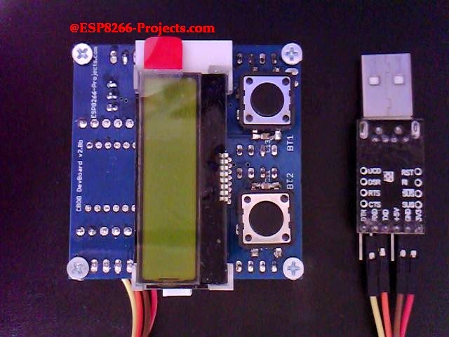
TOP View:
Bottom View:

Step 3: Schematics

As you can see from the schematic above, a true Development Board full of functions in a 5x5 size PCB, small enough to easy integrate in your hobbyist workplace ecosystem:
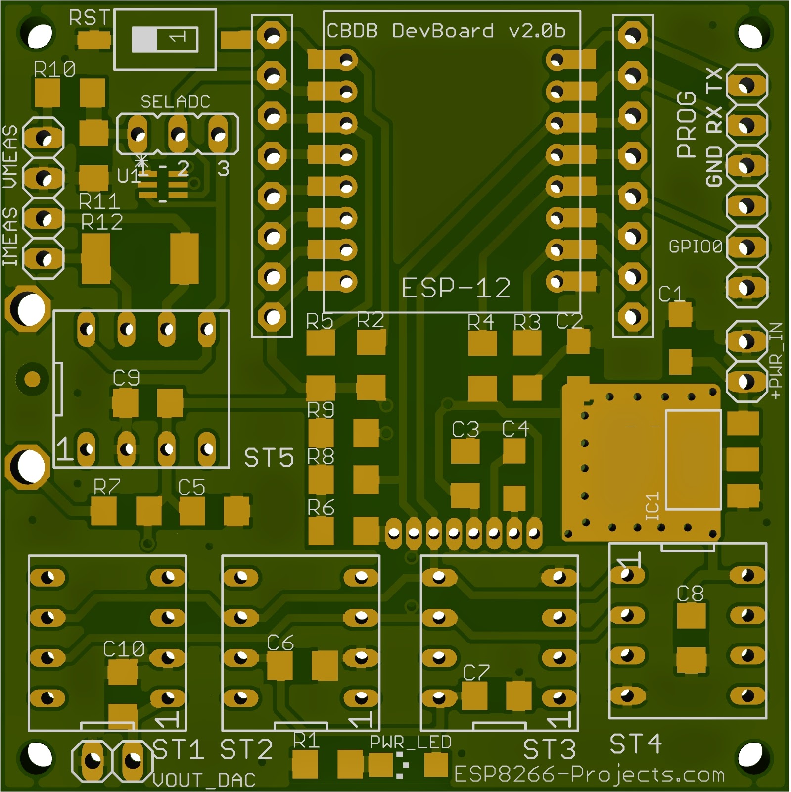
Latest design review PCBs of the fresh new ESP8266 Dev Board v.2 just landed on my desk and is definitely a next step in Experimenting in the IOT world. Designed with ease of use and flexibility in mind it will offer you endless hours of Experimenting, Programming and Developing your own projects:
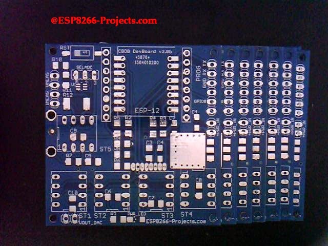
Step 4: Soldering and Testing PSU

After finished the SMD soldering, cleaning and cooling down, this is how is looking the ESP8266 CBDBv2 Evolution DevBoard, ready for testing the onboard regulator.
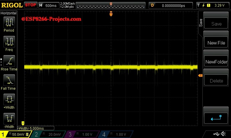
PSU regulator test was done with power supplied from a Li-Ion Battery pack and also from a standard 5V SMPS unit under a decent 500mA load. No overheating or nasty oscillations, looks good up to 800mA. At 800mA looks warm (38C) but the proper calculated double side heatsink area is doing the job right :).
I know it's a big debate this days about 1A requirement for ESP8266 Modules, but from all my experience and informations, at least with the ESP-07/12 Modules I had in my hands in the latest months, they were never exceed the 250mA margin. In fact, I have one module running for months now as a temperature logger/webserver and the power consumption looks constantly as in the picture below:

ESP-01 modules looks somehow different in a bad way. For some unforseen reasons some old ESP-01 modules that I also have cannot be programmed using power directly from my CP2102 USB Adapter, as ESP-07/12. Not enough juice for them.
Why? If I will find some extra time I will take a look at them. I have no more interest in them as very limited in term of I/O Capabitility.
If is anybody out there that has the answer, please share it with us.
Step 5: FIRMWARE Upload

Let's see is how easy is the process to upload Firmware and how long will takes to configure and start using CBCBv2 Development Board (code name Evolution).
It will come preconfigured with NodeMCU, so, if LUA is your desired programming language you can just start using it.
In case of firmware update needed or if you want to change the environment, it is a very easy process, similar with the one used for MPSM Board.
What we will need:
- CBDBv2 board
- USB adapter (take a look here for details)
- NodeMCU firmware
- NodeMCU Flasher ( firmware programmer for NodeMCU DEVKIT)
- ESPTool ( Bootloader firmware programmer)
For uploading the new firmware you have 2 different options to follow:
1. Using the clasic "jumper-style" procedure
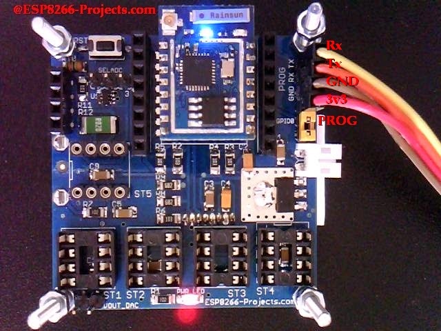
- connect CBDB Module with the USB Adapter (Tx, Rx, 3v3, GND), Set the PROG jumper in the Programming mode position (closed) and power on
- Start NodeMCU Flasher. Choose you USB adapter corresponding port
- Add from Config Menu latest previously downloaded firmware. It must start from 0x0000. Disable anything else.
- Go back on Operation tab. Power off your CBDB Module. Press FLASH Button. Power ON quick CBDB module. It will be recognised and will start flashing. Give it a second try if necessary.
- When finished succesfully A green OK checkmark will appear
- Power Off CBDB Module, Remove yellow jumper. Power back ON. Your CBDBv2 Board should be now programmed with the new NodeMCU Firmware.
Manual Firmware Upload Process
If you change very often the firmware or want a "hands-free" way to use CBDBv2 DevBoard, even with Arduino IDE or direct GCC/Eclipse programming then maybe you will prefer the second available procedure for uploading your firmware:
2. Using the Auto reset/bootloading mode:
Another great tool for uploading new firmware for your CBDBv2 DevBoard is esptool.
I want to thank themadinventor for such a great utility program and also want to thank for the received improvements to the members of the ESP8266 community, including pfalcon, tommie, 0ff and george-hopkins. Great job!
We will use in this example the CK version (thank you Christian) but any version of esptool that is supporting the RTS/DTR reset/bootloading mode must work ok. If you want to avoid compiling yourself the program you can download the binary file from here: esptool-bin.zip
Upload procedure:
- connect CBDB Module with the USB Adapter (Tx, Rx, RTS, DTR, 3v3, GND) and power on

- In Command Prompt Start esptool.exe program:
D:\ESPTool>esptool.exe -cp COM34 -cd ck -cf nodemcu_latest.bin
cp - Select the serial port device to use for communicating with the ESP.
cd - Select the reset method to use for resetting the board.
cf - Select the firmware file that you want to flash memory
Step 6: First Program
For further programming in LUA, it might be possible to do it directly
in your Serial Terminal Program but I will recomend you to use a more dedicated program for that, like LuaLoader or LuaUploader. I will stay with the latest one, for it's great flexibility and simplicity.
To run a quick test, you can just use the code snippets provided by LuaUploader at start-up. Select the piece of code that you want to run and press "Execute Selection" button.
- To quick setup your WIFI network :
       -- One time ESP Setup --
        wifi.setmode(wifi.STATION)
        wifi.sta.config ( "YOUR_WIFI_SSID" , "PASSWORD" )
        print(wifi.sta.getip())
For the Blinky test, just use a prepared LED as in the picture below. Be careful with Anode / catode orientation.
Insert it on previously used yellow jumper place (GPIO0) and run the code from below

         -- Blink using timer alarm --
         timerId = 0 -- we have seven timers! 0..6
         dly = 500 -- milliseconds
         ledPin = 3 -- 3=GPIO0
         gpio.mode(ledPin,gpio.OUTPUT)
         ledState = 0
         tmr.alarm( timerId, dly, 1, function()
             ledState = 1 - ledState;
             gpio.write(ledPin, ledState)
         end)
Step 7: ARDUINO IDE Integration
YES, it's true!
And YES, it is still in a early experimental statge but is working OK.
For the ones of you that are very familiar with the Arduino IDE environment and want to use it in the future I have some good news: CBDBv2 Evolution Development Board can be directly programmed with !
Just download Arduino IDE from here, add the CBDBv2 config files if you want auto-reset/bootloading or use generic ESP8266 for manual upload process and that's it!
Let's see the Blinky Example , Arduino IDE style:
// the setup function runs once when you press reset or power the board
void setup() {
  // initialize digital pin 15 as an output.
  pinMode(15, OUTPUT);
}
// the loop function runs over and over again forever
void loop() {
  digitalWrite(15, HIGH);   // turn the LED on (HIGH is the voltage level)
  delay(500);              // wait for 1/2 second
  digitalWrite(15, LOW);    // turn the LED off by making the voltage LOW
  delay(500);              // wait for 1/2 second
}
Step 8: CONCLUSIONS
Please keep in mind this is a experimental board, not a commercial product and is offered as it is. If it will burn your house, help the Aliens to abduct you or even eat your cat it's your problem not mine. The old enough ones to remember ALF will understand even deeper the disclaimer :)
For any new requests please feel free to use as usual: tech at esp8266-projects.com.
If you want for your own experiments to order bare PCBs only, you can also do it directly at the PCB House: http://dirtypcbs.com/view.php?share=5876&accesskey=3d0fd70d53d6dc20c0bf0255f67cde65
For more details about CBDB DevBoard project and other related projects please feel free to visit out website: http://www.esp8266-projects.com
Other conclusions...I have received from you a great feedback for all the articles and tutorials published so far and I am looking forward to hear your appreciations about this new project :)
THANK YOU ALL!!
Step 9: License and Credits
Arduino IDE is based on Wiring and Processing. It is developed and maintained by the Arduino team. The IDE is licensed under GPL, and the core libraries are licensed under LGPL.
The build used includes an xtensa gcc toolchain, which is also under GPL.
Espressif SDK included in this build is under Espressif Public License.
Esptool written by Christian Klippel is licensed under GPLv2, currently maintained by Ivan Grokhotkov: https://github.com/igrr/esptool-ck.
ESP8266 core support, ESP8266WiFi, Ticker, ESP8266WebServer libraries were written by Ivan Grokhotkov, ivan@esp8266.com.


