

Introduction: AVR Assembler Tutorial 8


Welcome to Tutorial 8!
In this short tutorial we are going to take a bit of a diversion from introducing new aspects of assembly language programming to show how to move our prototyping components to a separate "printed" circuit board. The reason is that, at this point, our main prototyping breadboard is getting crammed with so many chips, wires, buttons, and LEDs that it is getting difficult to test new things and since we eventually have to move the components to their own boards anyway, we might as well start now. Many of you are probably already proficient at the things we will cover in this tutorial and so you can look at this Tutorial as merely a relaxing break from coding.
So today we will move our dice roller ATmega328P and the accompanying pair of dice to an external board with connections to our main board for communication to it and for powering it. Aside from that, the wiring and functioning of the dice will be self-contained within that component.
You can probably predict from this that our eventual goal is to do this with each of the components we construct along the way so that when we are finished we can hide them all away into a nice looking package which will function via button presses without seeing all of the wires and internal workings.
We will spend most of this tutorial doing physical tasks like designing a circuit, mapping a prototyping board, and soldering stuff together, but there is a bit of programming we need to do at the end after we move things. The reason is that we are eventually going to be using the 2-wire Serial Interface to communicate between our main "master" controller and all of the "slave" controllers that make up the components of our overall project in this series of tutorials and, as you recall, in Tutorial 6 we invented a sort of Morse Code type method to communicate our dice rolls from the dice roller (Tutorial 4) to the Register Analyzer (Tutorial 5) which displayed the result of the dice roll in binary on 8 LEDs. Well that was just a "roll your own" method of communicating that I decided to use because, at that time, it was too early to get into 2-wire serial communication. We are now almost prepared to dive into the deep end of serial communication, and we will be doing that in Tutorial 10, but for now we need to anticipate that future development and re-wire our dice roller LED's in order to free up the two pins that we need for the serial communication.
These are the SCL and SDA pins on the ATmega328P. You can see by the pinout diagram that they are also called ADC5 and ADC4 when used in Analog-to-Digital conversions, they are called PCINT13 and PCINT12 when used as "Pin Change Interrupt" pins, and finally we generally call them PC5 and PC4 when simply considered as pins on PortC. Since we used these two pins as part of our dice roller for various reasons (the main ones being that it made coding easier and wiring to the LEDs on the board easier) we will now have to modify our code and re-wire it slightly to free up these pins for future communcation.
So we will begin by doing the designing, cutting, wiring, and soldering. Then we will re-write the dice roller to work with our new set up and finally test it to make sure it still works.
In order to complete this Tutorial you will need the following items:
- The standard stuff you always need that I am going to stop repeating all the time: your prototyping board, your copy of the datasheet and the instruction set, and your brains.
- A wireless circuit prototyping PCB board like this one: http://www.ebay.com/itm/191416297627 I am going to use the Measure Explorer 103RAWD version of this board: http://www.ebay.com/itm/103RAT-circuit-proto-proto... since I have a bunch of them on hand, but the 103RAW-0 version that I link to above will work just fine as well.
- Clippers, wires, solder, soldering iron, "helping hands" or whatever to hold stuff, etc. etc. etc. again, from here on out I am going to stop listing this stuff as well. If you have actually gotten this far in these Tutorials then you probably have all this stuff already.
Here is a link to the complete collection of my AVR assembler tutorials: https://www.instructables.com/id/Command-Line-AVR-T...
Step 1: Design a Wiring Diagram


The cool thing about the Measure Explorer boards is that if you take some time and map things out at the beginning you can save yourself a heck of a lot of wiring at the end. So we will begin by taking some time designing our layout before we start soldering anything. With this kind of board, you have to cut a bunch of connecting wires, which is not all that easy, but the result is a very nice compact board with a minimum mess of tangled wires.
The first thing we need to do is design our circuit so that it fits on the board. A nice way to do this is to download the map of the board and then use it to play around with different designs until you find one that works. Here is the layout for the ME-PB-103RAWD http://www.bluemelon.com/photo/3483513-T800600.jpg and here is the layout for the ME-PB-103RAW-0 http://www.bluemelon.com/photo/57107/2297363-T8006...
I have also attached these as pictures.
There are a number of ways to design the circuit. The first is simply to print out the map above, take a pen or pencil, and start drawing connections on it. You will probably want to fit your LEDs and ATmega328P and stuff on to the board itself first so that you know how much space they take, then draw them on the diagram, and from there you can try various wiring schemes.
The second way you could do it is the same as the first except you find a computer program that will map the wiring for you using the latest topological algorithms.
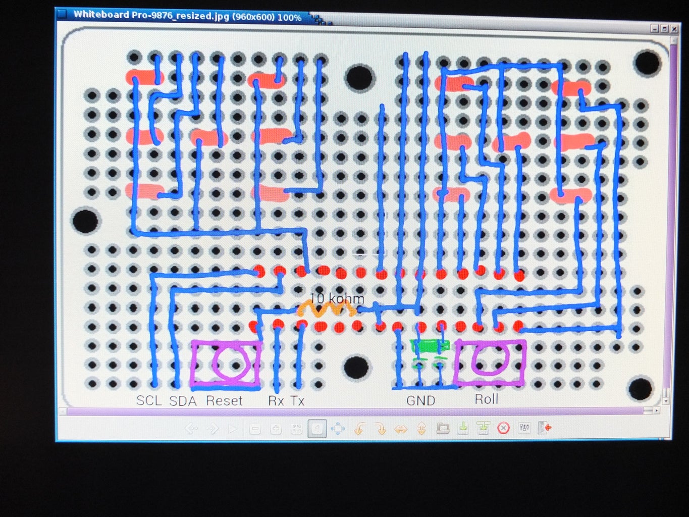
Finally, the way I did it. I set the components on the board first so I knew the size of things and where I wanted things. Then I downloaded an Android app called "Whiteboard" onto my Galaxy Tab4, loaded the board map onto it, and then went to the local pub and played around with designs over a few pints of Black Ghost Oatmeal Stout. :)
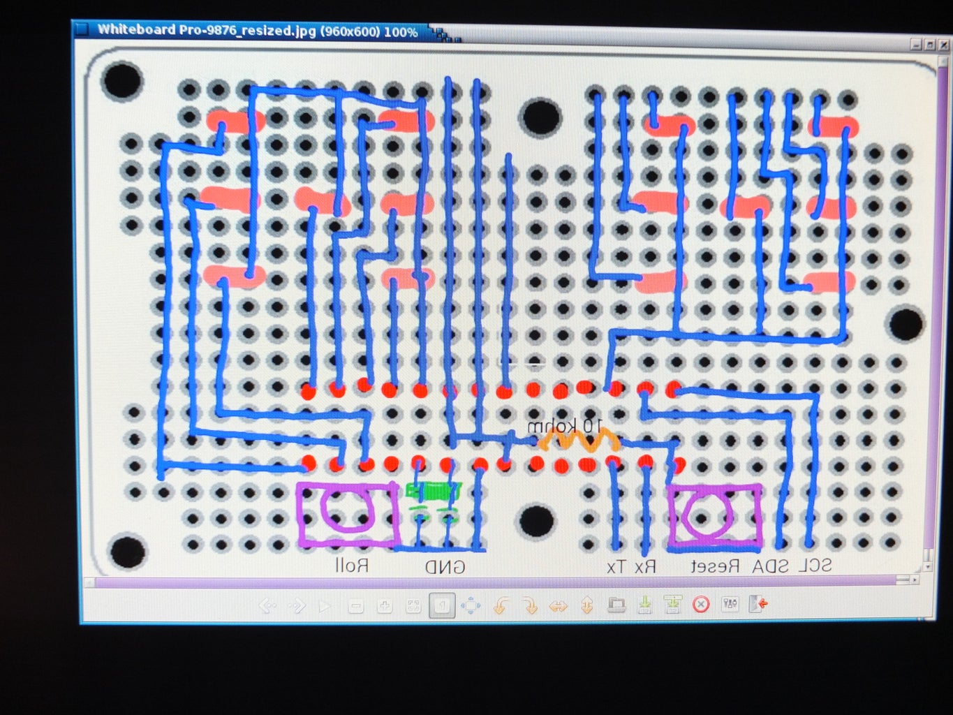
I show the result of this in the last two pictures. The nice thing about drawing it out this way is that when you look at it with your image viewer you can click "flip horozontal" and it will flip the image over giving you the wiring diagram for the other side of the board! Very convenient for our next step.
Step 2: Cut Out the Circuit on the Board


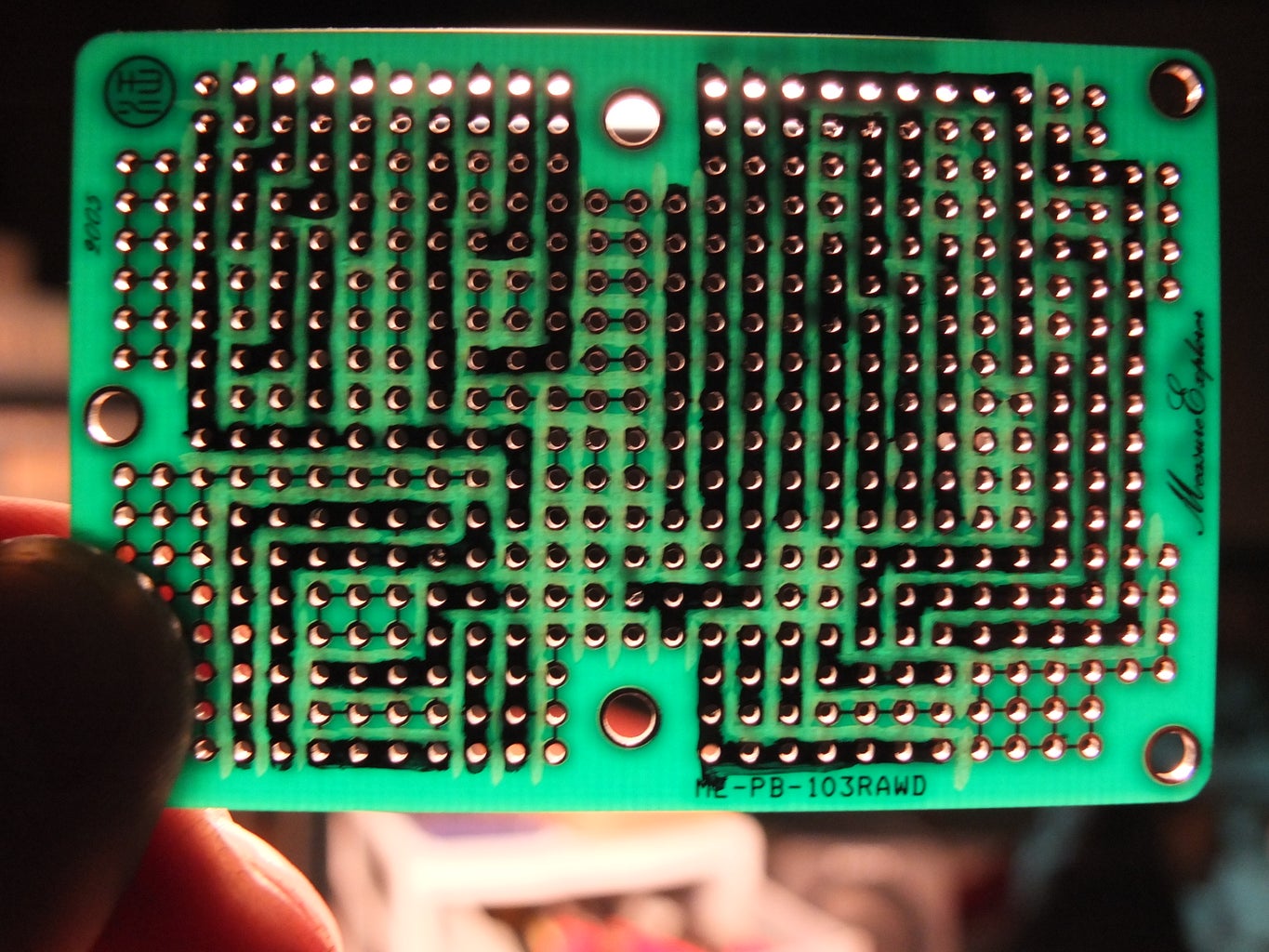
First take a sharpie and, using your layout that you mapped out in the previous step, draw your circuit on the board. I.e. draw lines to represent the wires. Don't draw anything in terms of components, just the connecting wires as show in the first picture. Notice that when you screw up (and if you are anything like me you will screw up things plenty of times in these steps) you can use an eraser and erase the line. Do this for both sides of the board.
Next you need to cut the connections around the lines. If you look closely at the board you will see that every pin hole is connected to the 4 adjacent ones on both sides of the board so that all of the holes on the board are connected to each other when you begin. So you need to cut along both sides of each of your wires to isolate them. The most common way to do this cutting is with an Exacto knife. But I suck at Exacto knives and would probably cut myself. So I use a Dremel with a thin cutting tool attachment. I wish I had some kind of grinding attachment that came to a sharp point since that would work best -- but I don't have one like that so I used the cutting saw attachment. (Note added: After finishing this project I found that the smaller "heavy duty cutting wheel" heads for Dremels work the best, they look like little circles of sandpaper and they work like the cutting tool shown here except that they are smaller diameter and so it is much easier to see and control where you are cutting)
Along the way it is useful to hold the board up to the light and make sure that the wires are actually cut. You may be annoyed at the fact that there are connections on both sides of the board so you have to repeat the cutting process again with the other side, but I think you will see the point of this by the time you are finished. I made plenty of mistakes cutting wires that shouldn't have been cut and having the other side still connected turns out to be nice.
It will take quite a bit of time and patience to cut the circuit into the board but it is kind of fun once you get good at it.
Step 3: Solder the Components and Test
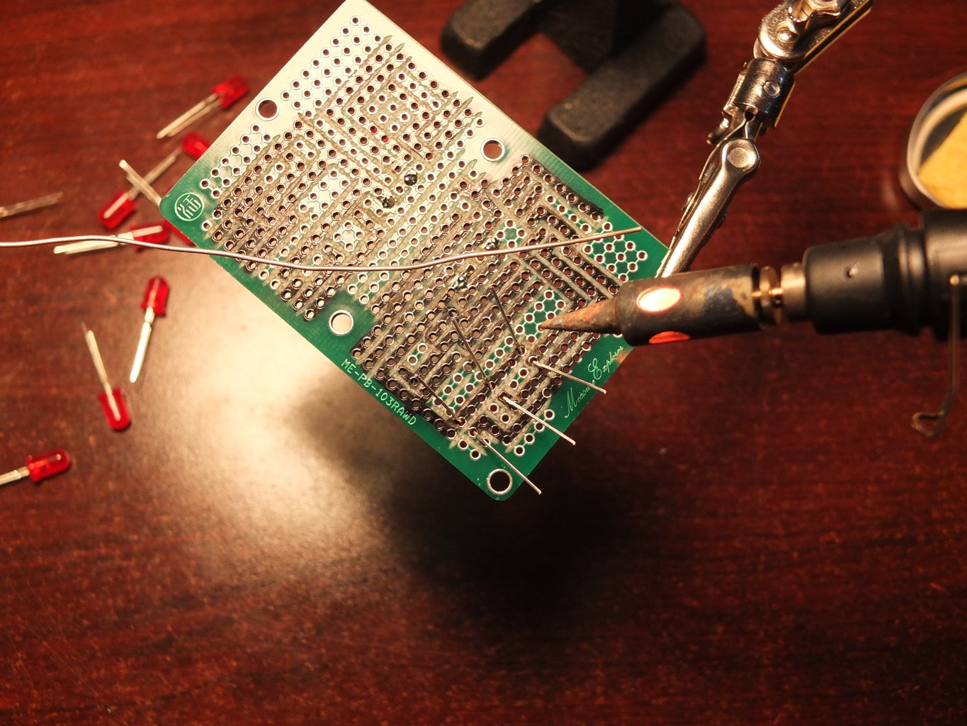


Now that you have isolated all of the wires in your circuit board you can start soldering on the individual components.
I first soldered on the LEDs for one of the dice, then I took positive and negative leads from my breadboard and tested the connections for each LED to make sure that they are isolated from each other and that they work.
Similarly with the other die.
Then wire the resistor to each die, and the 10K resistor on the back of the board.
Then attach the crystal oscillator, 22pf caps, pushbuttons, and ATmega328P. You may want to solder a chip socket and then fit your ATmega328P into that so that you can remove it if you want and reuse it in something else. I just soldered my chip to the board since I know what we are eventually building with all of these tutorials and I know I will like it enough that I won't want to take the chip out.
Notice, by looking at the back of the board, the way that we attached the headers. I used long pin headers and bend them horozontal so that they don't stick up out of the board. This is so that I can eventually cover the board to the level of the pushbuttons and LEDs with a container and not have headers getting in the way. We have a header for Tx,Rx so we can program the chip, we have a header for SDA,SCL so we can use 2-wire communication later on. and we have a 3 pin header for AVCC, AREF, GND on the other side of the board. I have all of the ground pins and VCC pins wired together on the chip so we only need one power input.
Finally once everything is wired, we wire die 1 to die2 the way we did on the breadboard so that we can control both dice with only 9 pins.
Now we need to modify our code so that it will control this new setup.
Step 4: Assembly Code and Video
I have attached the assembly code and the video of the dice roller in operation.
All I did was take the code for our dice roller from Tutorial 6, modify the pins to match the new layout, and remove the communications subroutine since we will be writing a new one in Tutorial 10.
Next time we will be breaking out our keypad again and learning how to control 7-segment displays.
See you then!


Participated in the
Make it Glow!

Participated in the
Formlabs Contest


